
Method and system for coordination of admission control in transport networks

a technology of transport network and admission control, applied in data switching networks, frequency-division multiplexes, instruments, etc., can solve the problems of low bandwidth expectations, packet loss, delay, or jitter,

Active Publication Date: 2010-07-08
BRITISH TELECOMM PLC
View PDF2 Cites 11 Cited by
  • Summary
  • Abstract
  • Description
  • Claims
  • Application Information

AI Technical Summary

Benefits of technology

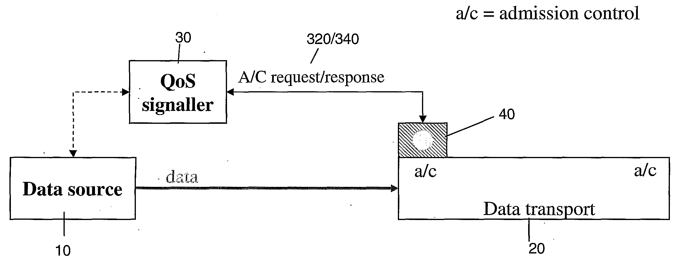
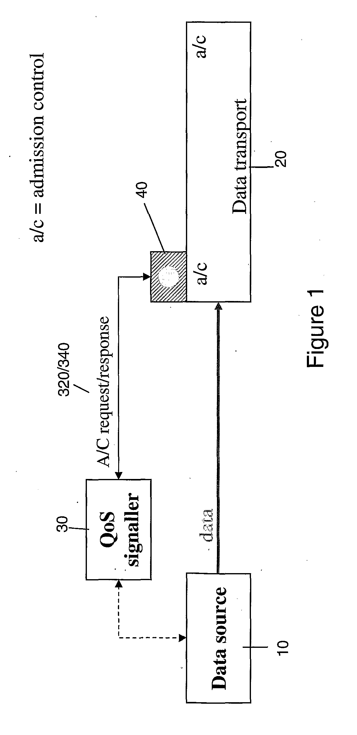
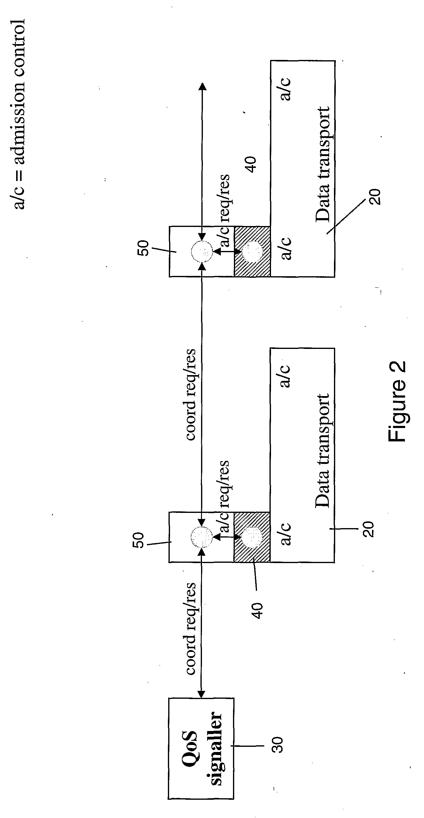
[0022]In view of the above, the present invention provides a coordination layer of coordinating entities provided intermediate the admission control interfaces of the transport network domains, and any QoS signaller which signals QoS requests on behalf of the application layer. The coordination layer acts to distribute an admission control request across the multiple transport network domains by the use of coordination request messages containing the admission control request being forwarded through the coordination layer of coordinating entities. At each coordinating entity the admission control request is passed on to the admission control interface of the transport network which the coordinating entity serves, and an admission control response obtained. This admission control response is then combined with admission control responses from the other domains which are propagated through the coordination layer via coordination messages. The result is that the coordination layer acts to combine the various admission control responses into a combined response, which can be provided back to the QoS signaller (or other requesting entity). Thus, coordination of admission control across multiple transport network domains is achieved, without a QoS signaller having to contact each individual domain.
[0024]As noted above, the first aspect of the invention provides the advantage that coordination across multiple domains can be achieved, by admission control responses being merged into a single, combined response. Moreover, the coordination entities may be used to coordinate admission control irrespective of the QoS architectures employed by the individual transport networks, by virtue of the coordinator entities sitting above the transport network domains in a separate coordination layer. In this respect, the admission control requests and responses preferably comprise a QoS description, but that description can be in almost any form. Moreover, the coordination messages exchanged within the coordination layer are agnostic to the form of QoS description used.
[0026]In another embodiment the coordinator entity operates in a non-blocking mode, wherein a received coordination request message containing an admission control request is forwarded on to a next coordinator entity for a next-hop transport network domain prior to an admission control response being obtained from the network domain for which the coordinator entity acts. Such operation allows for admission control requests to be propagated to all the domains as quickly as possible.
[0031]Preferably, the requested QoS type comprises an end-to-end type of service, being QoS types understood by the sending and receiving applications, rather than the particular transport networks. In preferred embodiments of the invention the end-to-end QoS type is selected from the group comprising: elastic; real-time tolerant; and real-time intolerant. With such an arrangement end-to-end QoS definitions can be mapped to transport network specific QoS, thus providing for further flexibility in application design and production.

Problems solved by technology

For example, an email application may require high reliability, but have low expectations for bandwidth, delay, or jitter, whereas a video conferencing application will have much higher expectations in respect of delay, jitter, and bandwidth, but can tolerate a degree of packet loss.
However, packet loss is unlikely as long as traffic is within its specified envelope.
Whilst the Integrated Services and Differentiated Services architectures appear sound in theory, in practice they have proved difficult to apply, principally because they require the sending application to know the particular quality of service architecture used by the transport network.
Due to the proliferation of different technologies, therefore, QoS requester mechanisms have not been built into applications typically, due to the necessity to build in compatibility with all the different QoS architectures.
Moreover, with the different types of QoS there is at present no integrated technique to allow for the coordination of admission control decisions over a large scale multi-domain network, where the individual domains may be employing different QoS architectures.
RSVP as described above provides for the coordination of QoS in an Integrated Services architecture where every node is RSVP enabled, but is inherently limited to operation with RSVP-enabled nodes.
However, where multiple domains are involved which use different QoS architectures, e.g. a DiffServ architecture, or do not make any QoS reservations or guarantees at all, then RSVP is not able to provide co-ordination.

Method used


Image

  • Method and system for coordination of admission control in transport networks
  • Method and system for coordination of admission control in transport networks
  • Method and system for coordination of admission control in transport networks

Examples


first embodiment

[0071]A more detailed description of the operation of the “blocking mode” variant of the first embodiment will now be described, with respect to FIGS. 11 to 13, and 18 and 19.

[0072]As noted above, in blocking mode the admission control requests are served by the particular transport network domain for which a co-ordinator entity is acting, before the co-ordinator entity forwards on the admission control request to a next hop co-ordinator. FIG. 11 illustrates a state diagram of the operation of a co-ordinator entity acting in “blocking mode”.

[0073]After power up and initialisation, a co-ordinator entity 50 acting in blocking mode enters an idle state 110 in which it awaits the receipt of a co-ordination request message co-ord (req). A co-ordination request message co-ord (req) may be received from any of a QoS signaller 30 (if the co-ordinator is a first hop co-ordinator for a particular flow) or from another co-ordinator entity 50 in the co-ordination layer. Typically, a co-ordinati...

second embodiment

[0112]An example of the above is shown in FIGS. 21 and 23, wherein in order for an IP flow to pass from a sending application 2101 to a receiving application 2102, it must traverse multiple transport networks TN12114, TN22116, and TN32124, TN42126, TN52134, and TN62136. However, these transport networks are themselves administratively arranged into administrative domains with transport networks TN1 and TN2 being within the BT administrative domain 2110, transport networks TN3 and TN4 being within the FT administrative domain 2120, and transport networks TN5 and TN6 being within the DT administrative domain 2130. Whilst within any particular administrative domain comprising a collection of transport networks it will be relatively straightforward to allow a co-ordinator entity to know the addresses of other co-ordinator entities in the same domain, it is more problematic for a co-ordinator entity within one administrative domain to learn the address of co-ordinator entities within oth...

third embodiment

[0169]Additionally provided within the computer readable storage medium 410 are operating system software 4310, which is conventional, as well as domain gateway function software 4410, to enable the computer system to act as the domain gateway, and again which is conventional. In accordance with embodiments based on the invention, however, additionally provided is a flow ID to LSP or VC mapping table 4510, which maps flow IDs to identified LSPs or VCs, and which is referred to by the computer system and in particular the admission control process 4010 running thereon, when it receives a packet from the data source 10 with a particular flow ID, so as to know onto which of the LSPs or VCs it must put that packet. In this respect, when operating in this manner the computer system is a router of the transport network.


PUM


Abstract

The invention provides a coordination layer of coordinating entities provided intermediate the admission control interfaces of the transport network domains, and any QoS signaller which signals QoS requests on behalf of the application layer. The coordination layer acts to distribute an admission control request across the multiple transport network domains by the use of coordination request messages containing the admission control request being forwarded through the coordination layer of coordinating entities. At each coordinating entity the admission control request is passed on to the admission control interface of the transport network which the coordinating entity serves, and an admission control response obtained. This admission control response is then combined with admission control responses from the other domains which are propagated through the coordination layer via coordination messages. The result is that the coordination layer acts to combine the various admission control responses into a combined response, which can be provided back to the QoS signaller (or other requesting entity). Thus, coordination of admission control across multiple transport network domains is achieved, without a QoS signaller having to contact each individual domain.

Description

TECHNICAL FIELD[0001]The present invention relates to a method and system for coordinating request and / or response messages used for admission control requests and responses in a transport network. In particular, within embodiments of the invention quality of service messages can be collated and / or coordinated irrespective of the form of the quality of service definition used.BACKGROUND TO THE INVENTION AND PRIOR ART[0002]Within a network such as an Internet Protocol (IP) network a stream of packets from a source application to a destination application is called a flow. How the packets forming a flow should be dealt with by the transport network depends very much on the needs of the application, which in turn defines the needs of each flow. Four parameters can usually be defined to specify the performance metrics required of the transport network by a flow, being the bandwidth required (the data rate), delay (being how long the network takes to transport a packet from source to des...

Claims


Application Information

Patent Timeline
Patent Type & Authority Applications(United States)
IPC IPC(8): H04L12/56H04L12/54
CPCH04L12/5695H04L45/04H04L45/302H04L45/306H04L47/805H04L47/2491H04L47/724H04L47/783H04L47/801H04L47/18H04L47/70
Inventor CORLIANO, GABRIELEHOVELL, PETERBRISCOE, ROBERT J.
Owner BRITISH TELECOMM PLC
Learn More