Material for Anisotropic Magnet and Method of Manufacturing the same

a technology of anisotropic magnets and anisotropic materials, which is applied in the direction of magnetic materials, magnetic bodies, transportation and packaging, etc., can solve the problems of insufficient coercivity, insufficient remanence, and inability to achieve sufficient remanence, so as to improve remanence and coercivity, the melting point of grain boundary phases is relatively reduced, and the effect of smooth rotation

Active Publication Date: 2010-07-08
DAIDO STEEL CO LTD
View PDF7 Cites 18 Cited by
  • Summary
  • Abstract
  • Description
  • Claims
  • Application Information

AI Technical Summary

Benefits of technology

[0014]An object of the present invention is to improve coercivity of a material for anisotropic magnet containing the main component of Pr, without decreasing remanence.
[0029]Since the material for anisotropic magnet according to the present invention contains Pr as the main component, which increases coercivity more than Nd, high coercivity can be obtained. Further, since the amount of Pr is limited within 12.5 to 15.0 atomic percent, the coercivity is improved while practical problems, such as an increase of difficulty in hot plastic deforming and gall to a mold, are not occurred.
[0032]In the present invention, the axes of easy magnetization become easy to be aligned in a predetermined direction, with the result that the remanence can be increased. The reason is considered as follows: when Pr is used as the main component of the material for anisotropic magnet, the melting point of the grain boundary phases is relatively reduced and the crystal grains can be smoothly rotated. That is, the present invention makes it possible to improve coercivity without decreasing remanence due to specific characteristics of Pr and specific alignment mechanism of Pr during the hot plastic deforming.

Problems solved by technology

However, magnets in the related art have the following problems for use in motors that are used in a high-temperature environment.
It is difficult to improve both of the remanence and the coercivity.
H11 (1999)-329810 improves the maximum energy product ((BH)max) by particularly increasing the remanence, however, has a problem in that it can not obtain sufficient coercivity.
H2 (1990)-3210 can obtain high coercivity, however, has a problem in that they can not necessarily obtain sufficient remanence.

Method used


Image

  • Material for Anisotropic Magnet and Method of Manufacturing the same
  • Material for Anisotropic Magnet and Method of Manufacturing the same
  • Material for Anisotropic Magnet and Method of Manufacturing the same

Examples


example 1.1

1. Manufacturing Specimen

[0128]A molten alloy having a predetermined composition was rapidly-quenched. Then the obtained ribbon was pulverized, thereby alloy powder was obtained. The alloy powder was cold-pressed and the cold-pressed body was hot-formed. Further, hot plastic deforming was applied to the hot-formed body, with the result that a material for anisotropic magnet was obtained.

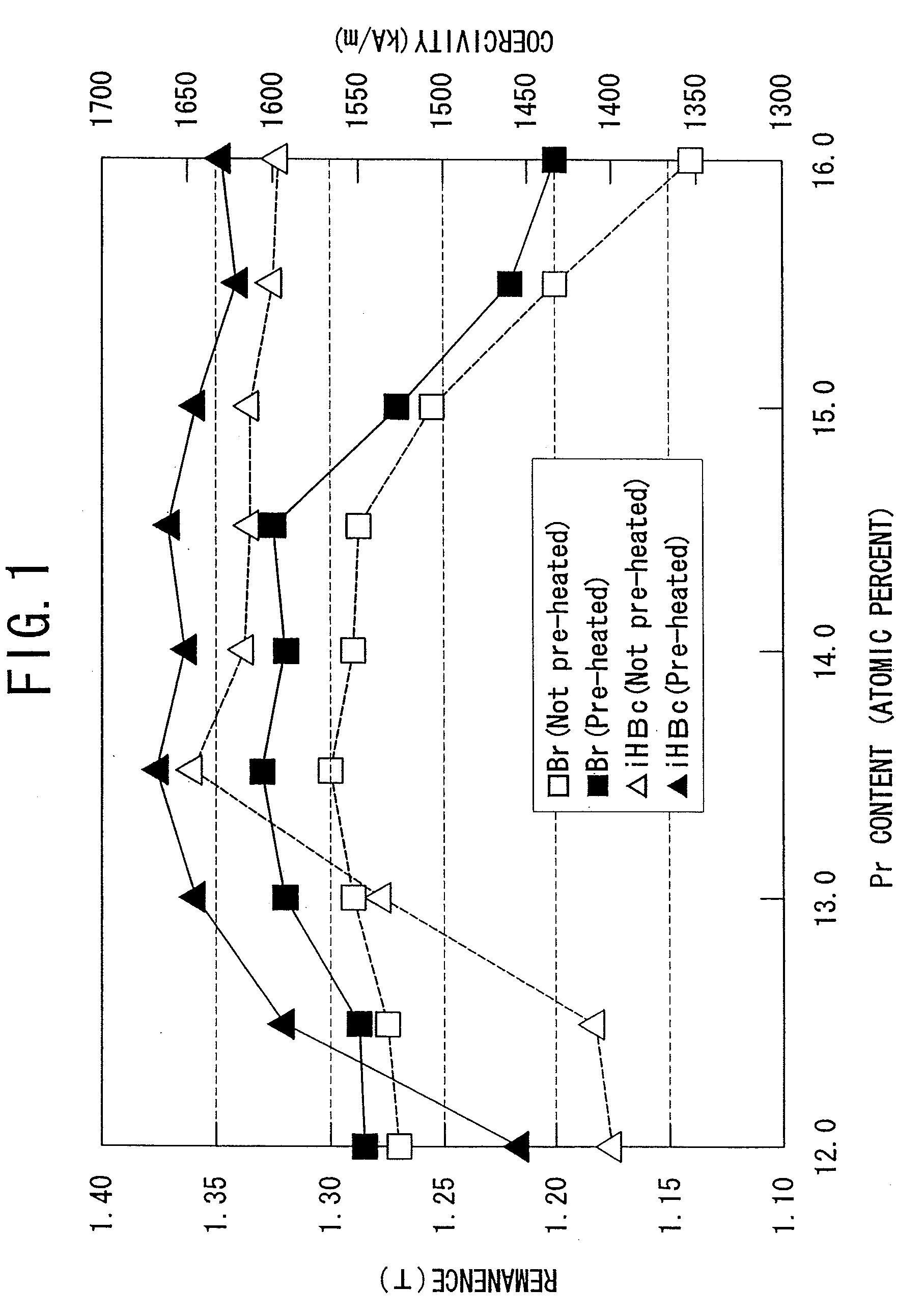
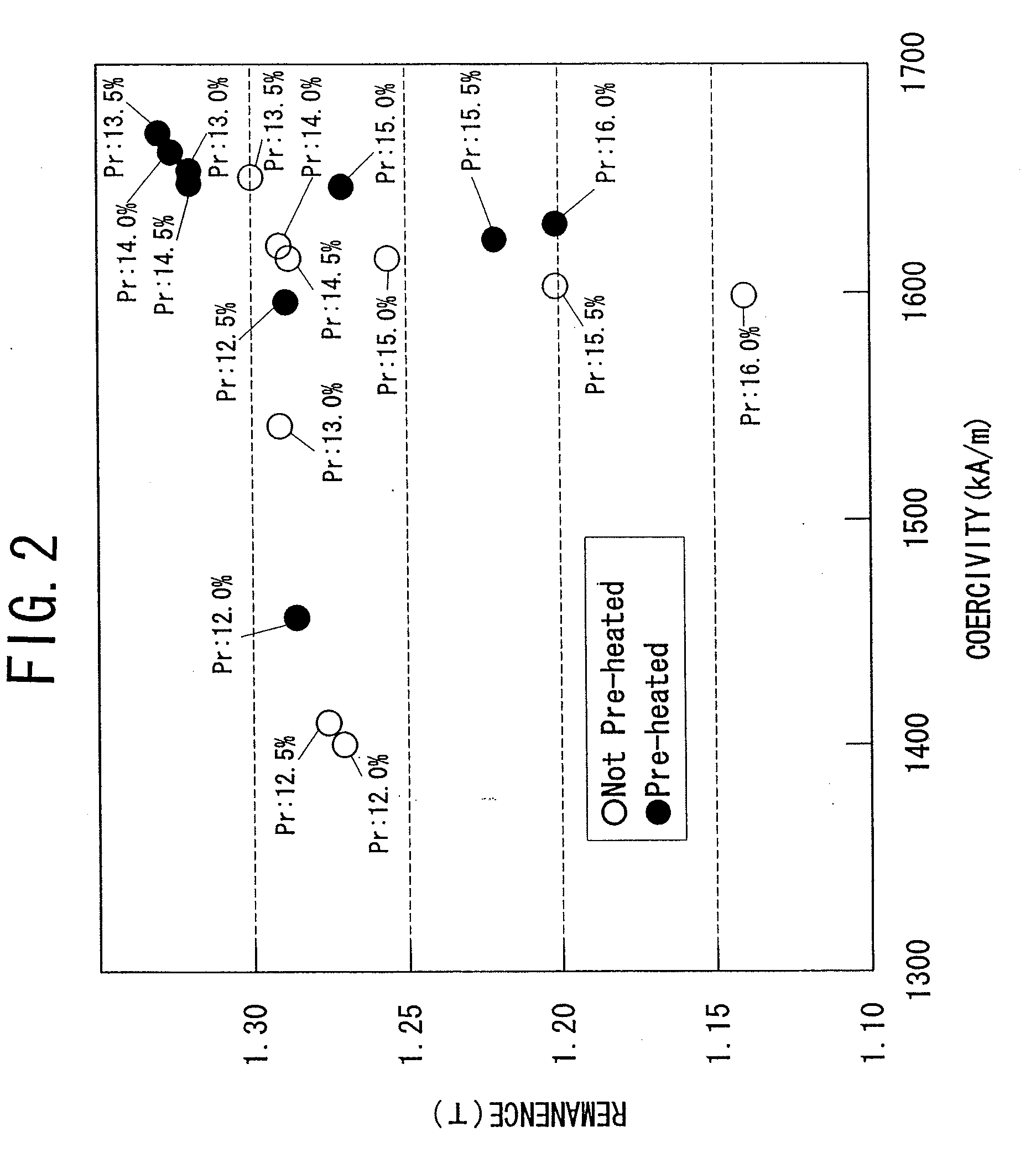
[0129]The composition of the alloy was PrxFe94.05-xB5.5Ga0.45 (x=12.0, 12.5, 13.0, 13.5, 14.0, 14.5, 15.0, 15.5, 16.0, including inevitable impurities).

[0130]Further, condition of pre-heating and hot-forming are respectively as follows:

[0131](1) (in the case that pre-heating is performed) pre-heating of 750° C.×10 minutes, and hot-press of 815° C. (a temperature of a mold); or,

[0132](2) (in the case that pre-heating is not performed) hot-press of 850° C. (a temperature of a mold).

2. Method of Test

[2.1 Magnetic Property]

[0133]The material for anisotropic magnet was magnetized and the magnetic properti...

example 1.2

1. Manufacturing Specimen

[0149]A material for anisotropic magnet was manufactured in the same method as the example 1.1, except that the composition was Pr13.09Fe81.51-yB5.4Gay (y=0, 0.1, 0.2, 0.3, 0.4, 0.5, 0.6, 0.7, 0.8, including inevitable impurities).

2. Method of Test

[0150]The material for anisotropic magnet was magnetized and the magnetic properties were measured by using a direct current BH tracer.

3. Result

[0151]FIG. 4 illustrates the relationship between the Ga content and the coercivity (iHc).

[0152]It can be seen from FIG. 4 that,

[0153](1) when the Ga content is under 0.1 atomic percent, the coercivity (iHc) extremely decreases;

[0154](2) when the Ga content is over 0.7 atomic percent, the coercivity (iHc) decreases;

[0155](3) in order to achieve high coercivity, it is preferable that the Ga content is 0.2 to 0.7 atomic percent and more preferably 0.4 to 0.5 atomic percent; and

[0156](4) in the case that the pre-heating is performed, coercivity is higher than the case of not p...

examples 2.1 to 2.21

Comparative Examples 2.1 to 2.5

1. Manufacturing Specimen

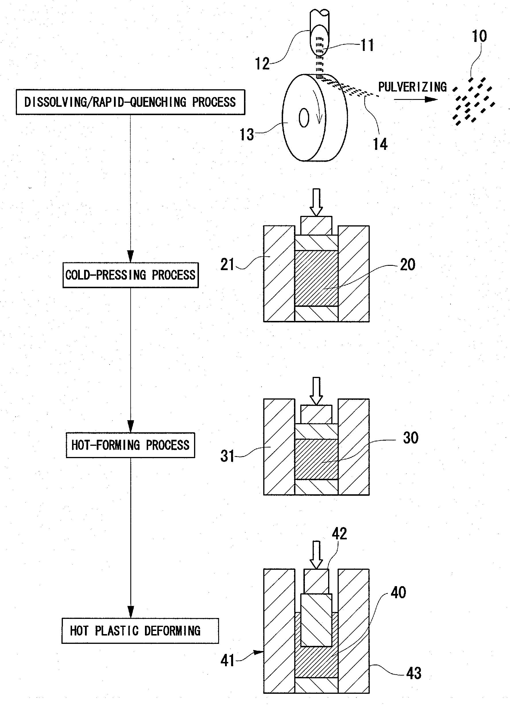
[0157]In accordance with the compositions (Examples 2.1 to 2.21, Comparative examples 2.1 to 2.5) shown in Table 1, material for anisotropic magnets were manufactured by the following manufacturing methods. FIG. 5 illustrates the processes of a method of manufacturing a material for anisotropic magnet.

[1.1 Dissolving / Rapid-Quenching / Pulverizing Process]

[0158]Predetermined amounts of various components of alloy materials were mixed and dissolved at 1000° C. or more. The molten alloy 11 was dropped and rapidly-quenched from an orifice 12 to a rotating roll 13 having high heat-removal property, and a ribbon 14 was manufactured. The circumferential speed of the rotating roll 13 was 18 to 20 m / s. The ribbon 14 was pulverized, thereby alloy powder 10 of flake form composed of fine crystal grains of 0.02 μm (20 nm) was obtained.

[1.2 Cold-Pressing Process]

[0159]Alloy powder 10 of 56 g was set in a cold press 21. The alloy powder was pr...


PUM

PropertyMeasurementUnit
temperatureaaaaaaaaaa

Abstract

A material for anisotropic magnet, comprising,(1) a Pr-T-B—Ga-based composition containing Pr: 12.5 to 15.0 atomic percent, B: 4.5 to 6.5 atomic percent, Ga: 0.1 to 0.7 atomic percent, and the balance of T and inevitable impurities, wherein T is Fe or obtained by substituting Co for a portion of the Fe; and having,(2) a degree of magnetic alignment of 0.92 or more, wherein the degree of magnetic alignment is defined by remanence (Br) / saturation magnetization (Js); and(3) a crystal grain diameter of 1 μm or less.

Description

[0001]This is a Continuation-in-part of application Ser. No. 12 / 392,329, filed Feb. 25, 2009. The application Ser. No. 12 / 392,329 is pending.BACKGROUND OF THE INVENTION[0002]1. Field of the Invention[0003]The present invention relates to a material for anisotropic magnet that can be obtained by hot plastic deforming, and a method of manufacturing the same.[0004]2. Description of the Related Art[0005]Recently, for motors or electric generators, magnets (rare-earth magnets) including rare-earth elements, such as neodymium or samarium have been widely used. The reason the rare-earth magnets are used is that they have excellent magnetic properties and are relatively inexpensive. Coercivity (iHc) and remanence (Br) are considered as important factors in the magnetic properties.[0006]The coercivity is the magnitude of magnetic field that is needed to make magnetization zero. In general, it has been known that heat resistance is excellent when the coercivity is large.[0007]The remanence re...

Claims


Application Information

Patent Timeline
Patent Type & Authority Applications(United States)
IPC IPC(8): B22F3/24H01F1/055B22F3/12B22F9/00B22F1/068
CPCB22F1/0055B22F2998/10H01F41/0273H01F1/0576H01F1/0571C22C38/005C22C38/002C21D8/1261C21D8/1205B22F2999/00B22F3/04B22F3/16B22F2003/145B22F2009/048B22F3/20B22F2003/202B22F1/068
Inventor HIOKI, KEIKOYABUMI, TAKAOHASHINO, HAYATO
Owner DAIDO STEEL CO LTD
Why Eureka
Try Eureka