Method of adjusting nozzle clearance of liquid application apparatus, and liquid application apparatus

a technology of liquid application apparatus and nozzle clearance, which is applied in the direction of water supply installation, drawing-off water installations, instruments, etc., can solve the problems of inaccurate adjustment of nozzle clearance, inability to reproduce precisely nozzle clearance, and misalignment of nozzle and non-contact distance sensors, so as to reduce the influence caused by windings, accurately adjust nozzle clearance, and accurately obtain

Active Publication Date: 2010-07-15
MUSASHI ENG INC
View PDF4 Cites 12 Cited by
  • Summary
  • Abstract
  • Description
  • Claims
  • Application Information

AI Technical Summary

Benefits of technology

[0051]Moreover, according to the method of adjusting the nozzle clearance in the liquid application apparatus of the present invention, the nozzle contacting step of having the nozzle contacted the reference surface and the distance measuring step of measuring the distance from the non-contact distance sensor to the reference surface are carried out separately, when measuring the relative position between the nozzle and the non-contact distance sensor, instead of conventionally carrying out the distance measurement by the non-contact distance sensor at the same time of making the nozzle contacted with the measuring jig (the reference surface in the present invention). Therefore, a position of making the nozzle contacted and a position of measuring the distance by the non-contact distance sensor on the reference surface of the contact detection sensor are the same or made closer than conventional art, which enables decreasing the influence caused by windings, heaves of the measuring jigs or other, accurately obtaining information of the relative position between the nozzle and the non-contact distance sensor in the vertical direction and more accurately adjusting the nozzle clearance than conventional art.

Problems solved by technology

Such a case error will possibly cause the nozzle and non-contact distance sensor to be misaligned with each other in the direction of the nozzle clearance (Z-axial direction).
Even if the nozzle clearance is adjusted for the distance measured by the non-contact distance sensor to be the same as that which was before the nozzle replacement, the inaccurate alignment between the nozzle and non-contact distance sensor makes it impossible to reproduce precisely the nozzle clearance which was before the nozzle replacement.
So, accurate information on the Z-axial relative position between the nozzle and non-contact distance sensor cannot be provided, and thus the nozzle clearance cannot accurately be adjusted.
Also, since the position where the nozzle is in touch with the measuring jig and the position where the measurement by the non-contact distance sensor is made are separated from each other, a slight inclination of the measuring jig will result in a large Z-axial misalignment and tremendous amounts of labor and cost are required for production of a high-precision measuring jig.
So, it is not possible to accurately measure the Z-axial alignment between the nozzle and measuring jig, and thus the nozzle clearance cannot be adjusted accurately.
Also, when the nozzle is put into touch with the measuring jig as above, it will possibly be damaged at the front end thereof, so that no acceptable sealant application can be assured.

Method used


Image

  • Method of adjusting nozzle clearance of liquid application apparatus, and liquid application apparatus
  • Method of adjusting nozzle clearance of liquid application apparatus, and liquid application apparatus
  • Method of adjusting nozzle clearance of liquid application apparatus, and liquid application apparatus

Examples


embodiment 1

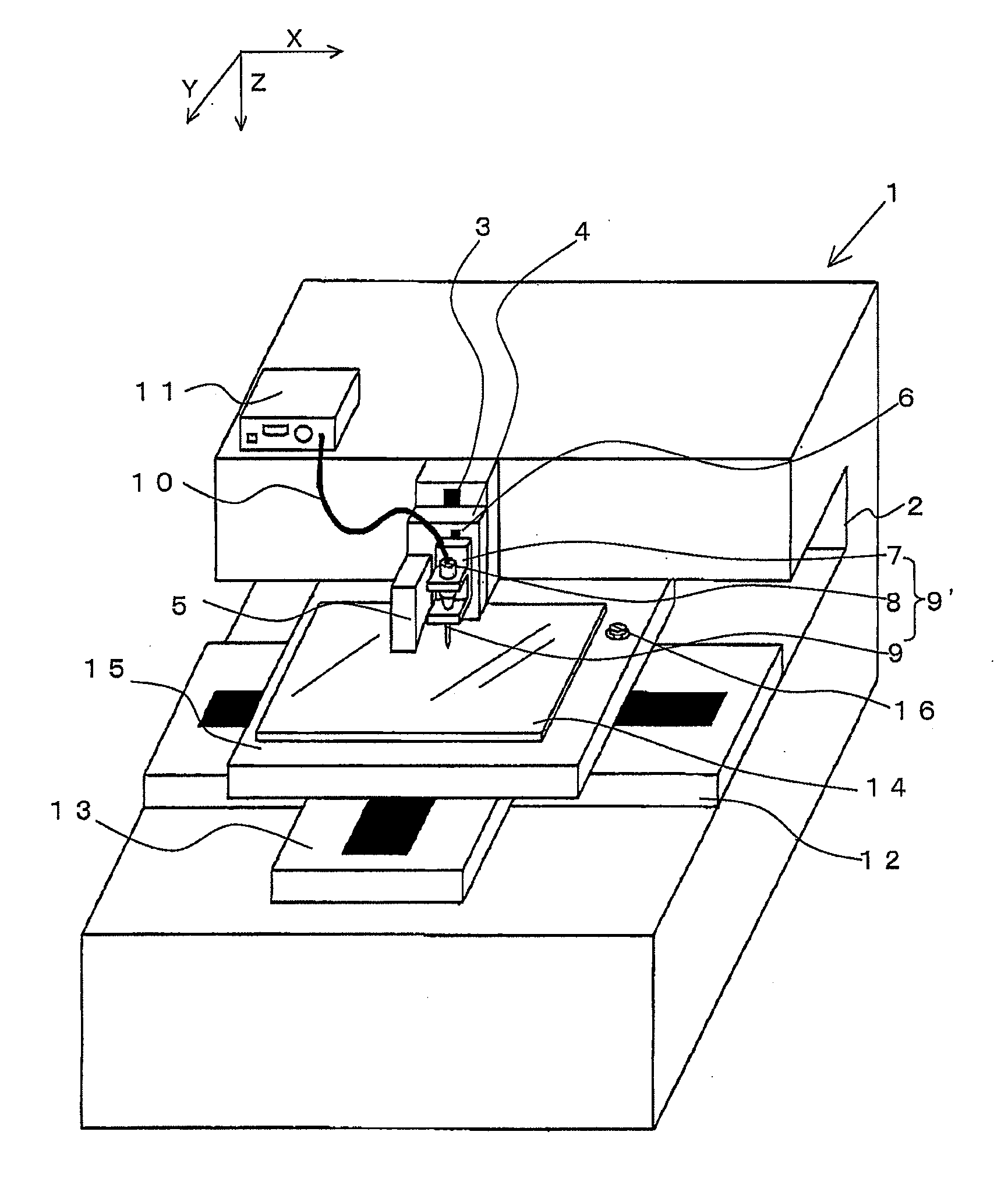
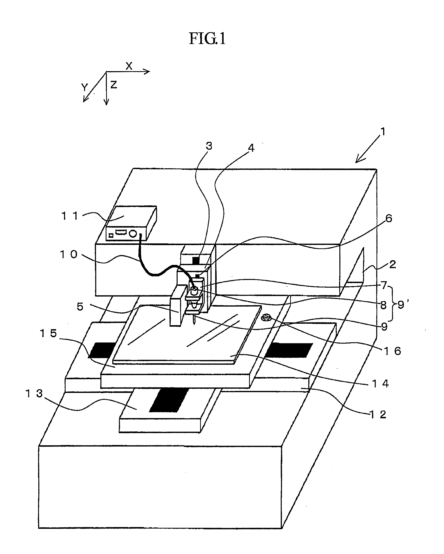
[0092]This embodiment is the liquid application apparatus (shown in FIG. 1) using the Z-axially moving table 3, sub Z-axially moving table 6 and touch sensor 16 as the vertical position changer. The nozzle clearance is adjusted as will be explained below with reference to the flow diagram shown in FIG. 3 and FIGS. 4 (a)-4(d).

[0093](1) Step 1 (Power-up):

[0094](2) Step 2 (Setting of liquid applying conditions):

[0095]The apparatus operator makes entry of liquid applying conditions such as a position where the application is to be started, pressure of air supplied from the application apparatus 11, nozzle clearance, etc.

[0096](3) Step 3 (Distance measurement step): As shown in FIG. 4(a), the X- and Y-axially moving tables 12 and 13 are driven for the laser displacement sensor 5 to come to just above the touch sensor 16, laser light is emitted from the laser displacement sensor 5 to the reference surface 19a of the touch sensor 16, and return light from the touch sensor 16 is detected by...

embodiment 2

[0120]There will be explained with reference to the flow diagram in FIG. 3 and the step chars in FIGS. 7 (a)-7(c) how to adjust the nozzle clearance in a sealant application apparatus (see FIG. 6) in which the Z-axially moving table 3 and touch sensor 6 are used as the vertical position changers according to another embodiment of the present invention. It should be noted that operations up to step 5 in FIG. 3 are effected as having been described above.

[0121]In step 6, the Z-axial relative position between the nozzle 9 and laser displacement sensor 5 is adjusted. In this adjustment, a Z-axial relative position between the nozzle and laser displacement sensor (distance Zn-Z1 from the front end of the nozzle 9 to the touch-sensor reference surface 19a when the distance from the laser displacement sensor 5 to the touch-sensor reference surface 19a is L1) is obtained based on the values (L1, Z1, Zn) measured in steps 3 and 5 as shown in FIGS. 7(a) and 7(b). So, a value Lc is measured ba...

embodiment 3

[0123]Here will be explained how to adjust the nozzle clearance in the sealant application apparatus shown in FIG. 1 by a method different from that in the embodiment 1. This embodiment 3 and embodiment 1 are different from each other as follows. In the embodiment 1, in step 5 where the nozzle 9 is moved into touch with the reference surface 19a, the Z-axially moving table 3 is driven to put the nozzle 9 into touch at the front end thereof with the reference surface 19a of the touch sensor 16. In this embodiment 3, however, the sub Z-axially moving table 6 is driven to put the nozzle 9 into touch at the front end with the reference surface 19a of the touch sensor 16. Further, in the embodiment 1, the Z-axially moving table 3 is driven to move the nozzle 9 vertically in step 7. In this embodiment 3, however, the sub Z-axially moving table 6 is driven to move the nozzle 9 vertically.

[0124]The nozzle clearance adjustment by this method will be explained below with reference to the flow...


PUM

PropertyMeasurementUnit
diameteraaaaaaaaaa
distanceaaaaaaaaaa
distance measurementaaaaaaaaaa

Abstract

A method of adjusting a clearance between a nozzle and a work to a desired value in a liquid application apparatus wherein a liquid discharged from the nozzle is applied to the work, comprises (a) a distance measurement step of measuring, by using a non-contact distance sensor positioned in parallel with the nozzle, a distance from the non-contact distance sensor to a reference surface of a contact detection sensor detecting a contact of the nozzle front end with the reference surface opposite to the nozzle front end, (b) a nozzle contacting step of making contacts with the nozzle front end and the reference surface of the contact detection sensor to obtain a positional information of the nozzle, (c) a distance measurement step of measuring, by the non-contact distance sensor, a distance from the non-contact distance sensor to the work before applying the liquid to the work, and (d) a step of adjusting a nozzle clearance to a desired value based on the relative positional information between the nozzle and the non-contact distance sensor determined by the distance measurement step (a) and the nozzle contacting step (b), and the distance determined by the distance measurement step (c), thereby to enable the nozzle clearance adjustment based on accurate information of the relative position between the nozzle and the non-contact distance sensor in the nozzle clearance direction, which is less influenced by the work's windings, heaves or others.

Description

[0001]This application claims the priority of the Japanese Patent Application No. 2005-345104 filed in the Japanese Patent Office on Nov. 30, 2005, the entirety of which is incorporated by reference herein.TECHNICAL FIELD[0002]The present invention generally relates to a liquid application apparatus used in production of liquid crystal display, semiconductors, etc., and more particularly, to a method of adjusting, to a desired value, the nozzle clearance which is a distance from a discharge port of a nozzle of the liquid application apparatus to a substrate to which a liquid is to be applied (hereinafter referred to simply as “work”) and a liquid application apparatus adapted so that the nozzle clearance is so adjustable.BACKGROUND ART[0003]Generally, the display panel of the liquid crystal display is produced by applying a sealing material or sealant in the form of a frame to a glass substrate, bonding another glass substrate to the sealed glass plate from above and filling liquid ...

Claims


Application Information

Patent Timeline
Patent Type & Authority Applications(United States)
IPC IPC(8): B23P6/00
CPCG02F1/1303G02F1/1339B05C5/0216H01L21/68H01L21/6715Y10T137/0402Y10T137/598B05D1/00B05C11/00B05C5/00
Inventor IKUSHIMA, KAZUMASA
Owner MUSASHI ENG INC
Why Eureka
Try Eureka