Supercharge Your Innovation With Domain-Expert AI Agents!

Organic el element and a method for manufacturing the organic el element

a technology manufacturing methods, which is applied in the field of organic el elements, can solve the problems of disconnection formation in the cathode electrode, poor step coverage of the method, etc., and achieve the effect of preventing water invasion

Active Publication Date: 2010-07-15
ULVAC INC
View PDF7 Cites 0 Cited by
  • Summary
  • Abstract
  • Description
  • Claims
  • Application Information

AI Technical Summary

Benefits of technology

The present invention provides a technology for forming an MgAg film on an electron injection layer by sputtering, which can be used in an organic EL element. This technology solves the problem of previous methods where the electron injection layer was not sufficiently dense and a protective film could not be formed on its surface. The invention also provides a method for manufacturing an organic EL element with a cathode electrode layer that is transparent and can be used in a top emission type. The use of a thin film of MgAg and a matrix organic material in the electron injection layer can also be achieved. Overall, the invention provides a more effective solution for forming a high-quality MgAg film in an organic EL element.

Problems solved by technology

However, although omitted in FIG. 6, since there are actually steps on a surface of the organic EL element 101 and the vapor deposition method exhibits a poor step coverage, there is a problem in that disconnection is formed in the cathode electrode layer 107 at shadowed portions around the projected portions of the steps.

Method used


Image

  • Organic el element and a method for manufacturing the organic el element
  • Organic el element and a method for manufacturing the organic el element
  • Organic el element and a method for manufacturing the organic el element

Examples


Embodiment Construction

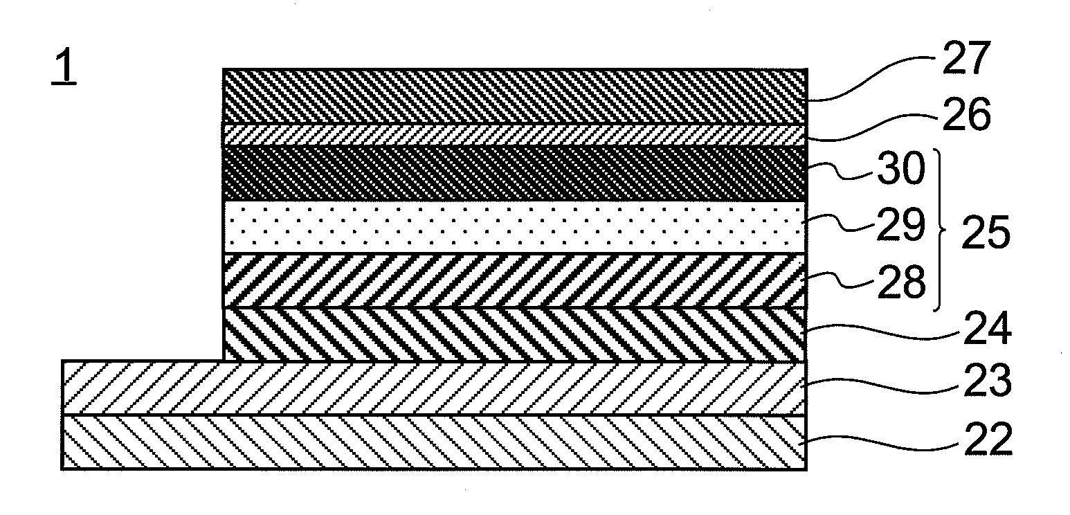
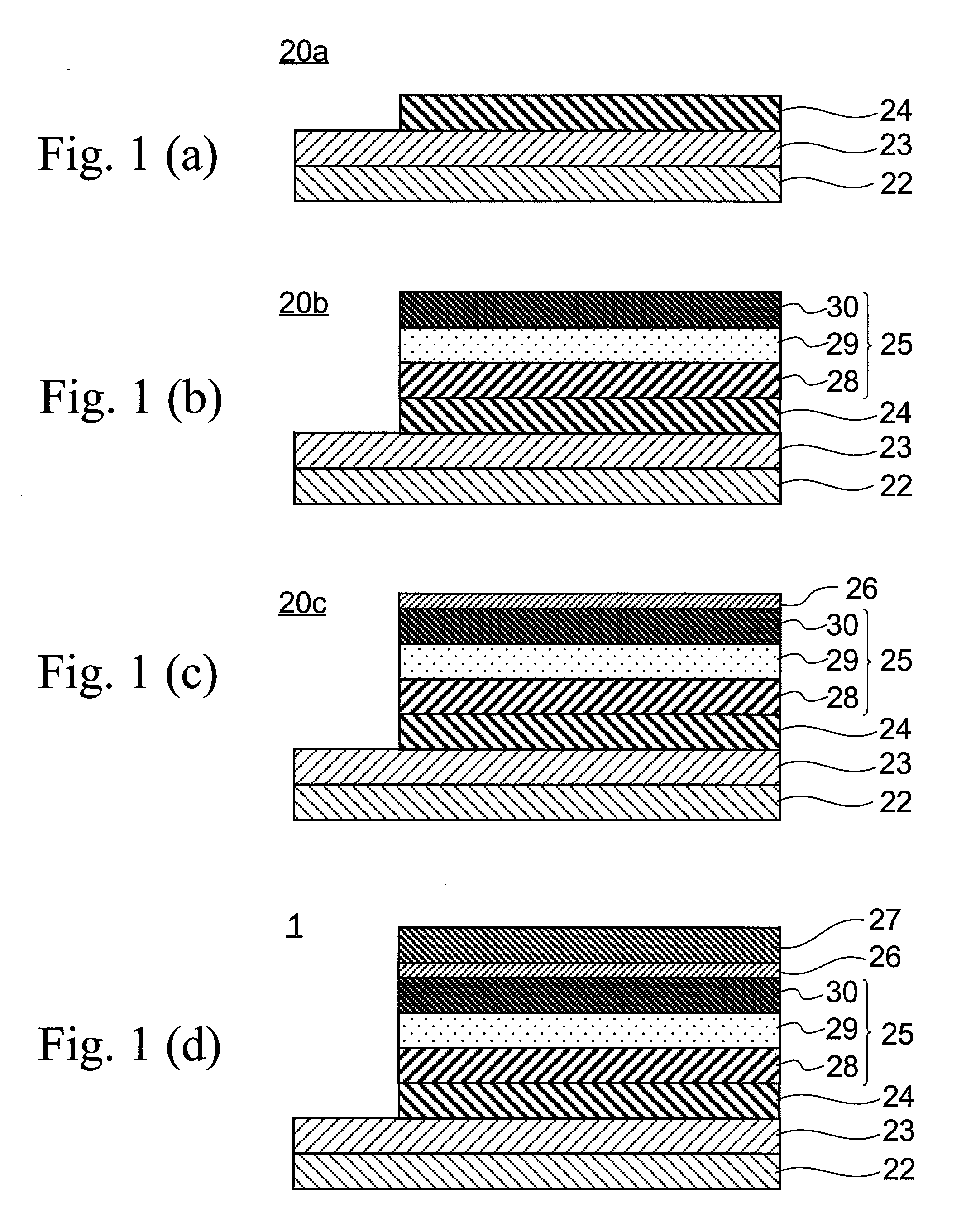
[0045]FIG. 1(d) is a sectional view of the organic EL element 1 of the present invention.

[0046]This organic EL element 1 has a plate-like substrate 22. An anode electrode layer 23, a hole injection layer 24, an organic light-emitting portion 25, an electron injection layer 26 and a cathode electrode layer 27 are formed on the substrate 22 in this order.

[0047]The organic light-emitting portion 25 is constituted by a hole transport layer 28 in contact with the hole injection layer 24, an electron transport layer 30 in contact with the electron injection layer 26, and a light-emitting layer 29 sandwiched between the hole transport layer 28 and the electron transport layer 30. When a positive voltage and a negative electrode are applied to the anode electrode layer 23 and the cathode electrode layer 27, respectively, holes are injected from the hole injection layer 24 into the hole transport layer 28, while electrons are injected from the electron injection layer 26 into the electrode t...


PUM


Abstract

A dense cathode electrode layer having a step coverage is to be formed on an electron injection layer. The electron injection layer in which fine particles of an electron injection material is dispersed in an organic thin film having an electron transport property is formed by vapor co-depositing the electron transport material and the electron injection material; and a cathode electrode layer made of an alloy layer of MgAg is formed by a sputtering method. Since lower portions of the fine particles of the electron injection material dispersed in the surface of the organic thin film are buried in the organic thin film, the electron injection particles are not peeled off even if sputtering particles collide with the electron injection particles, and the upper portions are in contact with the cathode electrode layer formed by sputtering particles.

Description

[0001]This application is a continuation application of International Application No. PCT / JP2008 / 067450, filed Sep. 26, 2008, which claims priority to Japan Patent Application No. 2007-258773, filed Oct. 2, 2007. The entire disclosures of the prior applications are herein incorporated by reference in their entireties.TECHNICAL FIELD[0002]The present invention generally relates to a technical field of the organic EL elements; and the invention more particularly relates to a technology for manufacturing a display device suitable for a top-emission-type organic EL element.BACKGROUND OF THE INVENTION[0003]A conventional organic EL element is shown by a reference numeral 101 in FIG. 6.[0004]This organic EL element 101 possesses a substrate 102. An anode electrode layer 103, a hole injection layer 104, an organic light-emitting portion 105 and an electron injection layer 106 and a cathode electrode layer 107 are formed on the substrate 102 in this order.[0005]When a positive voltage and a...

Claims


Application Information

Patent Timeline
Patent Type & Authority Applications(United States)
IPC IPC(8): H01L51/52H01L51/56
CPCH01L51/5092H01L2251/5315H01L51/5234H10K50/171H10K50/828H10K2102/3026
Inventor NEGISHI, TOSHIO
Owner ULVAC INC
Features
  • R&D
  • Intellectual Property
  • Life Sciences
  • Materials
  • Tech Scout
  • Unparalleled Data Quality
  • Higher Quality Content
  • 60% Fewer Hallucinations
Learn More