Continuously-Arranged Sensor System, Network Unit, and Sensor Unit

a sensor system and network unit technology, applied in the field of continuous arrangement of sensor systems, network units, and sensor units, can solve the problems of signal synchronization, delay in time in the transmission of various kinds of sensor information,

Inactive Publication Date: 2010-07-15
KEYENCE
View PDF14 Cites 4 Cited by
  • Summary
  • Abstract
  • Description
  • Claims
  • Application Information

AI Technical Summary

Benefits of technology

[0020]In a continuously-arranged sensor system according to the present invention, the determination signal and information about sensor detection performed by each sensor unit are transmitted to a network unit side via a serial transmission unit. When the determination signal of sensor is added to the serial-transmitted information about sensor detection (sensor information), the determination signal and the information about detection of the sensor information can be synchronized with eac...

Problems solved by technology

However, in the configuration described in Japanese Patent Application Laid-Open No. 2004-295276, although the sensor determination signal can be transmitted to the network unit side without delay, a delay in time occurs in the transmission of various kinds of sensor information via a serial signal.
Therefore, there is a problem in that the sensor information and the determination signal cannot be synchronized with ...

Method used


Image

  • Continuously-Arranged Sensor System, Network Unit, and Sensor Unit
  • Continuously-Arranged Sensor System, Network Unit, and Sensor Unit
  • Continuously-Arranged Sensor System, Network Unit, and Sensor Unit

Examples


first embodiment

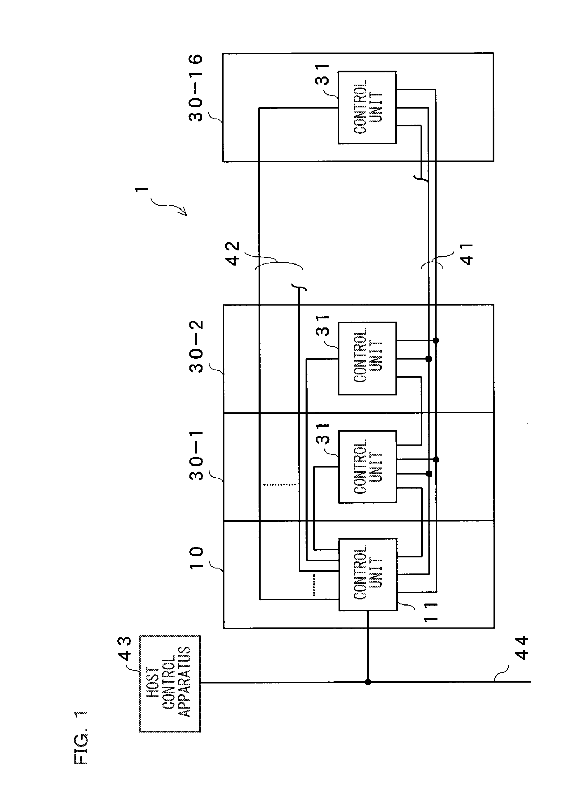
[0046]FIG. 1 is a figure showing an entire configuration of a continuously-arranged sensor system according to the first embodiment of the present invention. The continuously-arranged sensor system 1 includes at least one sensor unit connected to a network unit 10. In this embodiment, a series of sixteen sensor units 30-1 to 30-16 are connected to the network unit 10. These units are electrically connected via a serial transmission line 41 or a parallel transmission line 42. The serial transmission line 41 is configured to include at least two serial transmission lines. The parallel transmission line 42 is connected to each sensor unit via one signal line, and includes at least sixteen lines. Hereinafter, a direction toward the network unit 10 is referred to as upstream direction, and a direction toward the sensor unit 30-16 is referred to as downstream direction. The network unit 10 is adapted to collect signals transmitted from the sensor units 30-1 to 30-16 and to transmit a nece...

second embodiment

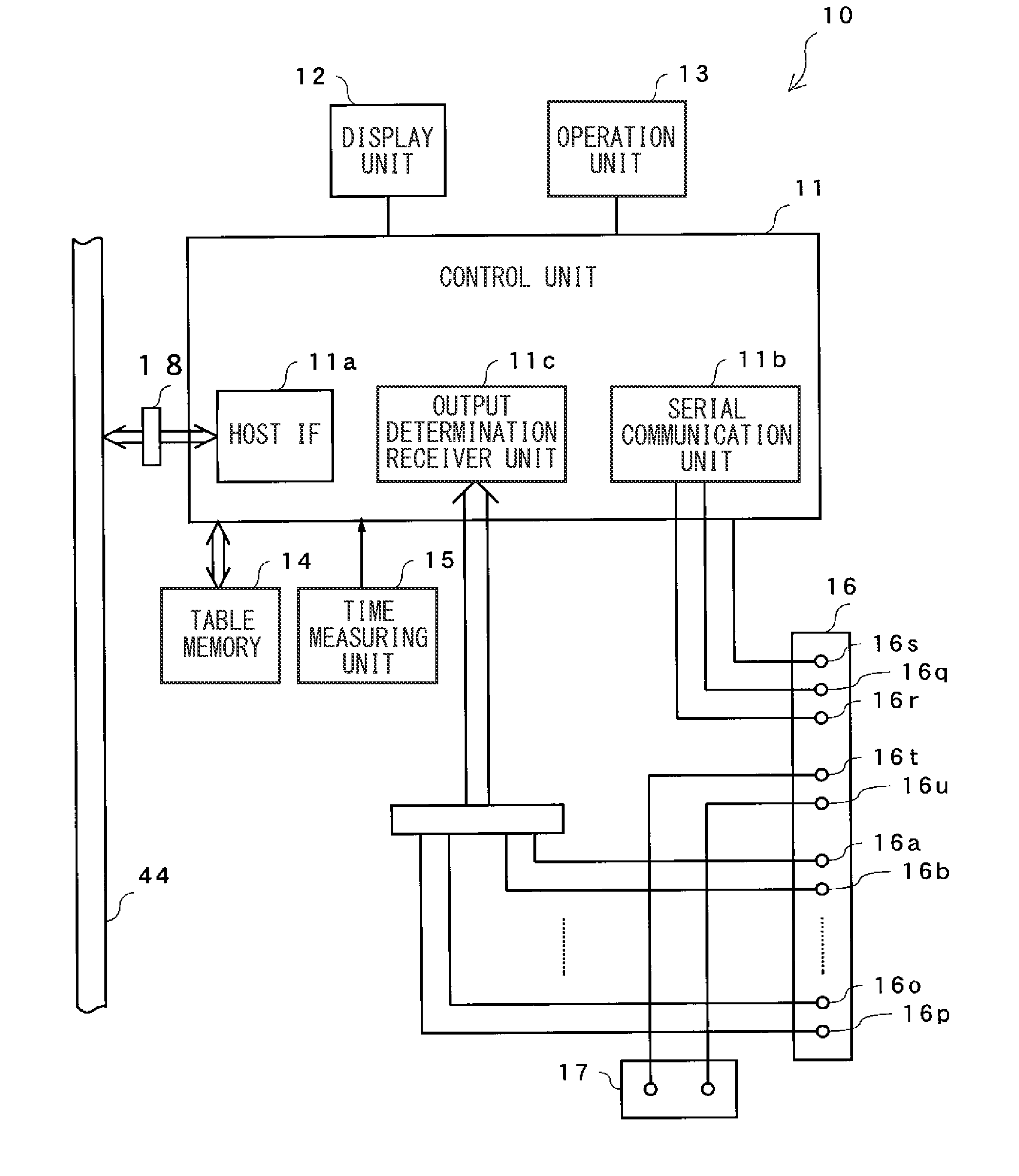
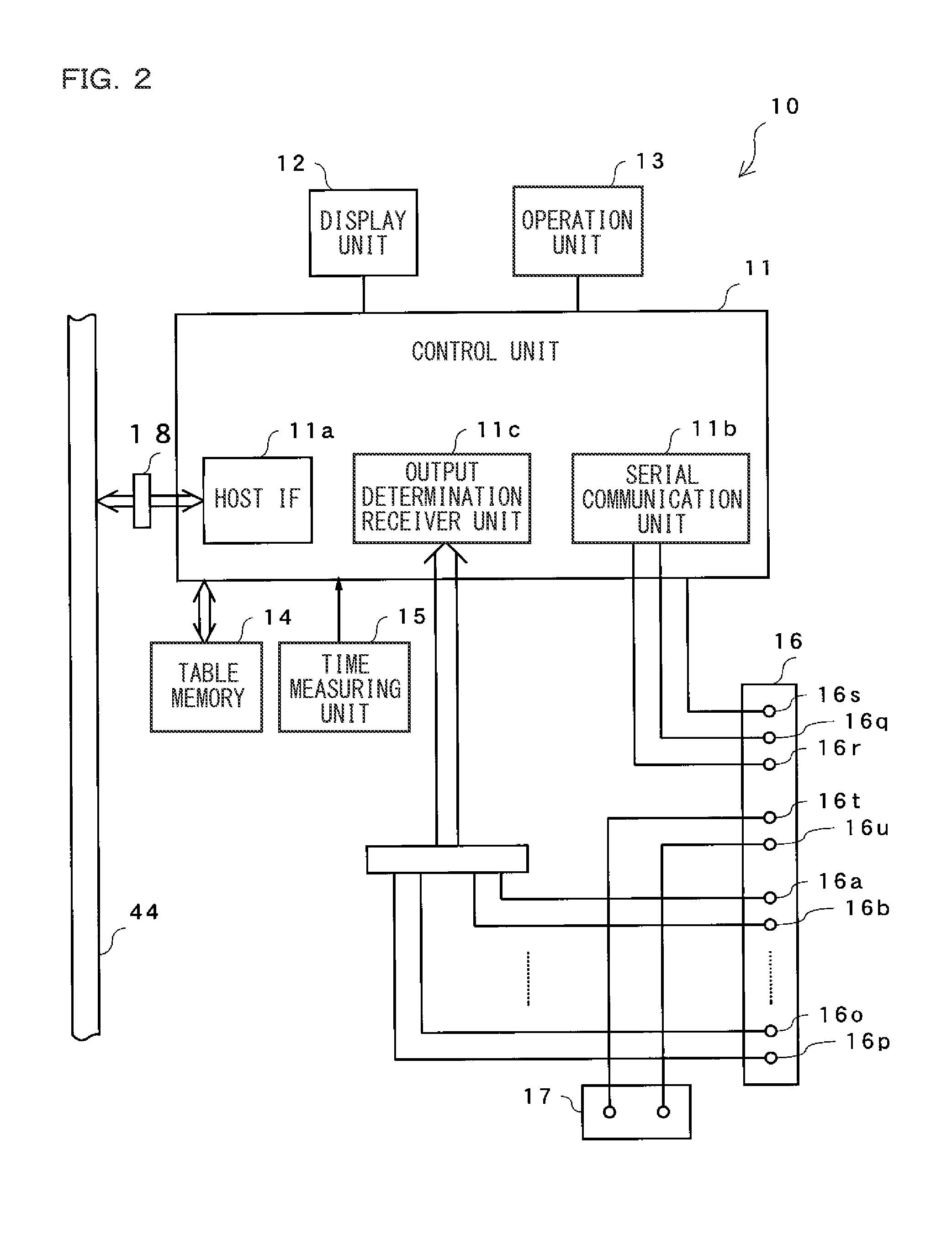
[0091]Subsequently, a continuously-arranged sensor system according to the second embodiment will be explained. Also in the present embodiment, sixteen sensor units 70-1 to 70-16 are connected to a network unit 60. The same sections as those of the above-described first embodiment are denoted with the same reference numerals, and the detailed description thereabout is omitted. As shown in FIG. 11, the network unit 60 has a control unit 61 provided with a synchronization signal transmission unit 11d. The synchronization signal transmission unit 11d transmits a synchronization signal to a particular sensor unit or all of the sensor units. The connector 16 has a terminal 16v for synchronization signal transmission in addition.

[0092]Also in the present embodiment, the sixteen sensor units 70-1 to 70-16 are coupled with each other, but each of the sixteen sensor units has the same configuration. Therefore, only the sensor unit 70-1 will be explained on the basis of the drawings. FIG. 12 ...


PUM


Abstract

A continuously-arranged sensor system is provided that can eliminate a shift in timing between a determination signal of each sensor unit and sensor information relating to the determination signal. The continuously-arranged sensor system includes a network unit and a plurality of sensor units, which are connected by a serial transmission line and a parallel transmission line. In accordance with a command sent from the network unit, each sensor unit transmits the determination signal and the sensor information, provided at the same time as the determination signal, to the network unit via the serial transmission line. Therefore, the network unit can obtain the determination signal and the sensor information exhibited at the same time.

Description

CROSS-REFERENCE TO RELATED APPLICATIONS[0001]The present application claims foreign priority based on Japanese Patent Application No. 2009-5230, filed Jan. 13, 2009, the contents of which is incorporated herein by reference.BACKGROUND OF THE INVENTION[0002]1. Field of the Invention[0003]The present invention relates to a continuously-arranged sensor system for monitoring a state of an object to be detected, and also relates to a network unit and a sensor unit used for the continuously-arranged sensor system.[0004]2. Description of the Background Art[0005]In a manufacturing process in an automated manufacturing line, a process state of a workpiece is monitored in order to reliably process the workpiece. Therefore, in the automated manufacturing line, many sensors are arranged in proximity to the workpiece (object to be detected) so as to monitor the process state, and the workpiece is processed while a determination signal of each sensor is monitored.[0006]In this kind of sensor syst...

Claims


Application Information

Patent Timeline
IPC IPC(8): G08C19/16
CPCH04Q9/00H04Q2209/30H04Q2209/823
Inventor FUKUMURA, KOJI
Owner KEYENCE
Why Eureka
Try Eureka