Liquid jet head chip, manufacturing method therefor, liquid jet head, and liquid jet recording apparatus

a liquid jet recording and manufacturing method technology, applied in metal-working equipment, printing, writing implements, etc., can solve the problems of difficulty in machining, inability to improve yield, and limit the pitch of the groove portion, so as to improve the quality of the liquid jet recording apparatus, the effect of small width and small channel pitch

Inactive Publication Date: 2010-07-15
SII PRINTEK
View PDF6 Cites 23 Cited by
  • Summary
  • Abstract
  • Description
  • Claims
  • Application Information

AI Technical Summary

Benefits of technology

[0012]The present invention is created in view of the above-mentioned situation, and it is an object of the present invention to provide a liquid jet head chip in which easiness in machining is improved and a narrow pitch of channels and high resolution are realized, a manufacturing method therefor, a liquid jet head, and a liquid jet recording apparatus.

Problems solved by technology

However, the thickness (width) of the dicer to be used in the dicing process has a limitation for securing strength or the like of the dicer, and hence there is a limitation in decreasing a pitch of the groove portion.
In order to decrease the width of the partition, high accuracy of machining is required, which causes difficulty in machining.
As a result, yield cannot be improved, and there may be a case where the machining cannot be performed.
Thus, it is difficult to decrease a pitch of the groove portion further in the future.

Method used


Image

  • Liquid jet head chip, manufacturing method therefor, liquid jet head, and liquid jet recording apparatus
  • Liquid jet head chip, manufacturing method therefor, liquid jet head, and liquid jet recording apparatus
  • Liquid jet head chip, manufacturing method therefor, liquid jet head, and liquid jet recording apparatus

Examples


first embodiment

[0047](Inkjet Printer)

[0048]Next, a first embodiment of the present invention is described with reference to the attached drawings. Note that, in this embodiment, an inkjet printer 1 that uses nonconductive oil ink (liquid) W for printing is described as an example of a liquid jet recording apparatus.

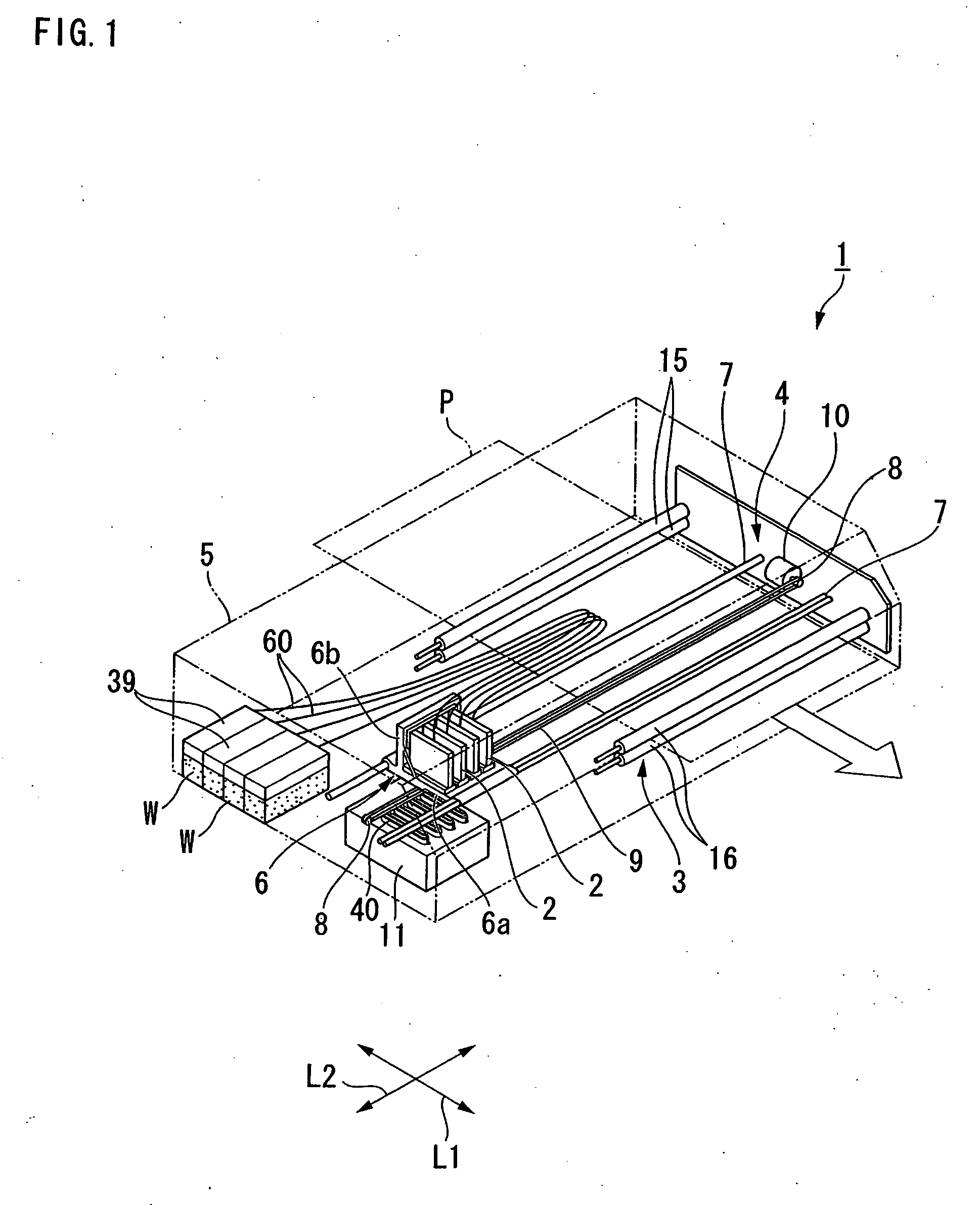
[0049]FIG. 1 is a perspective view illustrating a general structure of the inkjet printer 1.

[0050]As illustrated in FIG. 1, the inkjet printer 1 of this embodiment includes a plurality of inkjet heads (liquid jet heads) 2 for jetting ink W, a conveying unit 3 for conveying recording paper (recording medium) P in a predetermined conveying direction L1, and a moving unit 4 for moving the plurality of inkjet heads 2 in a reciprocating manner in the perpendicular direction L2 that is perpendicular to the conveying direction L1.

[0051]In other words, the inkjet printer 1 is a so-called shuttle type printer that conveys the recording paper P in the conveying direction L1 while the inkjet head ...

second embodiment

[0115]Next, a second embodiment of the present invention is described. FIGS. 9A and 9B are sectional views of a piezoelectric actuator 130 in the second embodiment, which correspond to FIGS. 5A and 5B. Note that the same structure as in the first embodiment described above is denoted by the same reference symbol so that overlapping description is omitted. The inkjet printer of this embodiment has a structure of mainly using conductive aqueous ink for recording.

[0116]As illustrated in FIGS. 9A and 9B, the piezoelectric actuator 130 of a head chip 121 according to this embodiment has the groove portion 35 that is divided into two channels. One channel constitutes a discharging channel 150 in which the ink W is filled, while the other channel constitutes a dummy channel 151 in which the ink W is not filled. In other words, the channels of this embodiment include the discharging channels 150 and the dummy channels 151 that are arranged alternately.

[0117]A deep groove portion 100 that is...

third embodiment

[0121]Next, a third embodiment of the present invention is described. FIG. 10 is a side view of a piezoelectric actuator 230 in the third embodiment. Note that the same structure as in the first embodiment described above is denoted by the same reference symbol so that overlapping description is omitted.

[0122]As illustrated in FIG. 10, the piezoelectric actuator 230 of a head chip 221 of this embodiment is different from that of the first embodiment described above concerning a shape of a first actuator plate 241a. As illustrated in FIG. 10, the first actuator plate 241a is a plate made of a piezoelectric material such as PZT similarly to the first actuator plate 41a (see FIG. 4) of the first embodiment described above. A plurality of groove portions 235 extending in the length direction (direction of the arrow X) are formed on the upper surface of the first actuator plate 241a and arranged in the lateral width direction (direction of the arrow Y) with predetermined spaces. Further,...


PUM

PropertyMeasurementUnit
widthaaaaaaaaaa
thicknessaaaaaaaaaa
width I2aaaaaaaaaa

Abstract

To provide a liquid jet head chip in which easiness in machining is improved and a narrow pitch of channels and high resolution are realized, a manufacturing method therefor, a liquid jet head, and a liquid jet recording apparatus. The liquid jet head chip includes a first actuator plate and a second actuator plate, each of which has partitions. The first actuator plate and the second actuator plate are superimposed with each other so that partitions thereof are arranged alternately. A discharging channel which is filled with ink is formed between the partition of the first actuator plate and the partition of the second actuator plate.

Description

BACKGROUND OF THE INVENTION[0001]1. Field of the Invention[0002]The present invention relates to a liquid jet head chip, a manufacturing method therefor, a liquid jet head, and a liquid jet recording apparatus having the liquid jet head.[0003]2. Description of the Related Art[0004]Conventionally, there is used an inkjet recording apparatus (liquid jet recording apparatus), which jets liquid, e.g., ink from nozzle holes (liquid jet holes) of a head chip (liquid jet head chip) so that ink drops are placed on a recording medium, to thereby print characters, images or the like. Each of the nozzle holes of the head chip is coupled to a piezoelectric actuator (liquid feeding portion). The piezoelectric actuator is provided with a plurality of groove portions (channels) in which the ink is filled. When a drive electrode that is provided to a partition for parting the groove portion is energized, the partition is deformed to squeeze out the ink so that the ink drop jets out from the nozzle ...

Claims


Application Information

Patent Timeline
Patent Type & Authority Applications(United States)
IPC IPC(8): B41J29/38B41J2/14B41J2/16
CPCB41J2/1631Y10T29/49401B41J2/1609B41J2/1632B41J2/1642B41J2/14209B41J2/1623B41J2/1626B41J2/1634
Inventor MAKISHIMA, TOMIHARU
Owner SII PRINTEK
Why Eureka
Try Eureka