Microscopy system with revolvable stage

a microscopy system and rotating stage technology, applied in the field of microscopy systems, can solve the problems of poor resolution of the z-axis direction in the stacked 3d image, affecting the spatial reliability of the high-resolution neural network image reconstructed, and limitation of the dimension of the pinhole and other mechanical or physical properties

Inactive Publication Date: 2010-07-15
NATIONAL TSING HUA UNIVERSITY
View PDF13 Cites 53 Cited by
  • Summary
  • Abstract
  • Description
  • Claims
  • Application Information

AI Technical Summary

Benefits of technology

[0007]Another object of the invention is to increasing the resolution of 3D image by means of fusing a plurality of sliced images of the sample acquired from different observation angles, especially increasing z-axis resolution of the 3D image of the sample.
[0008]It is a still further object of the invention to provide a microscopy system for increasing the depth resolution of the image by fusing two sliced images perpendicular to each other into one final image stack.

Problems solved by technology

However, the Z-axis direction in the stacked 3D image has a much poor resolution (e.g., about 1.2 μm / slice) than in the X-axis and Y-axis directions (about 0.15 μm / pixel) under the limitation of the dimension of the pinhole and other mechanical or physical properties.
A poor resolved Z-axis direction hampers the spatial reliability of the high resolution neural network images reconstructed, especially when comparison of two different samples is necessary.
The same problem happens to the transmitted light microscope.

Method used


Image

  • Microscopy system with revolvable stage
  • Microscopy system with revolvable stage
  • Microscopy system with revolvable stage

Examples


first embodiment

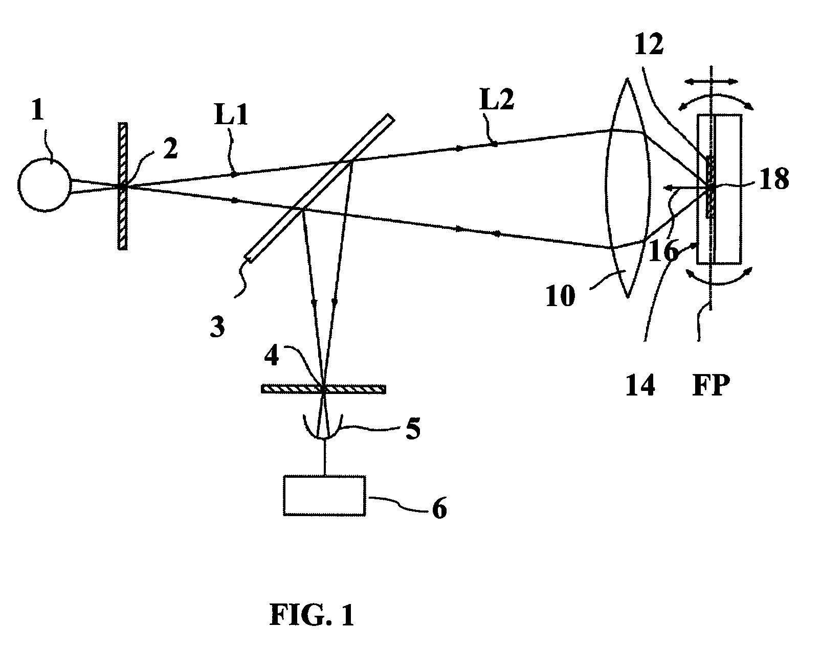
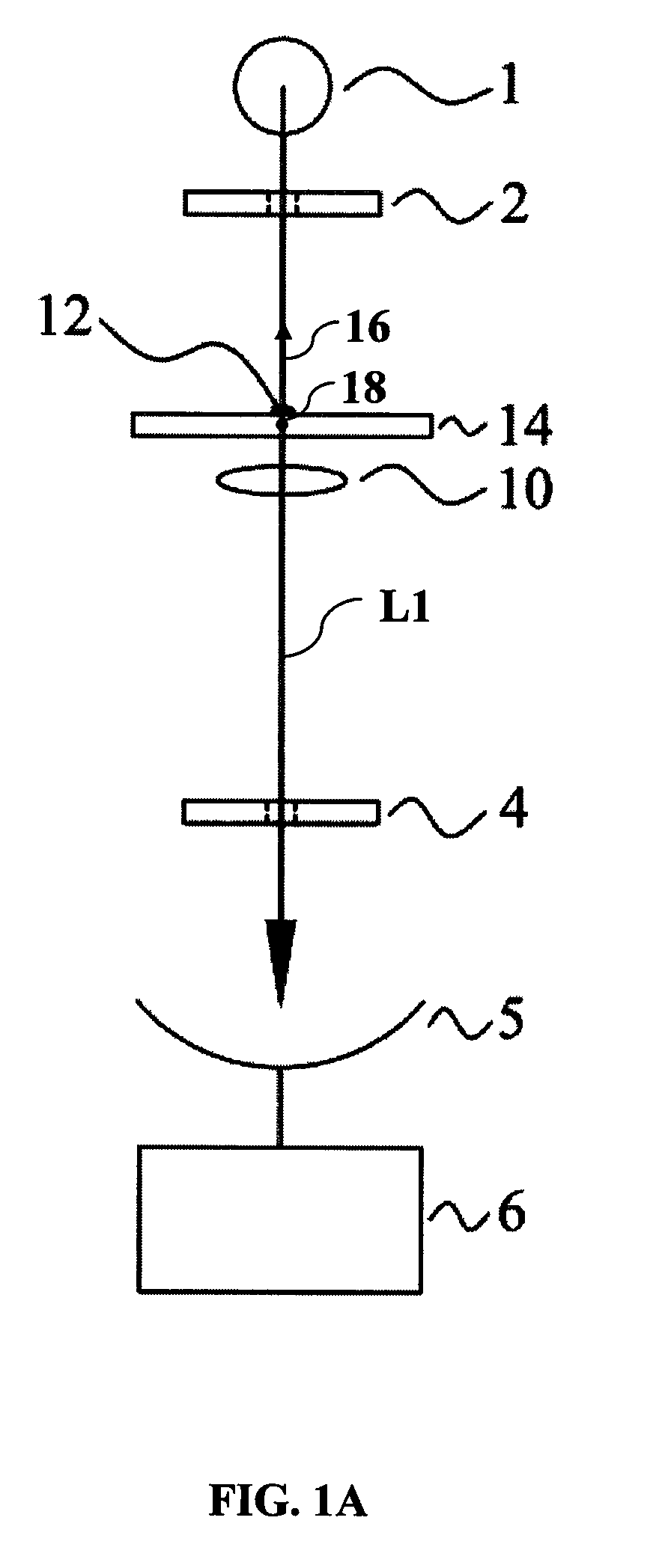
[0038]The present invention discloses a microscopy system. FIG. 1 is a schematic illustration showing a microscopy system according to the invention. FIG. 2 shows a first state of the microscopy system of FIG. 1. FIG. 3 shows a second state of the microscopy system of FIG. 1. Referring to FIGS. 1 to 3, the microscopy system of this embodiment includes an image focusing module 10 and a stage 14 for holding a sample 12.

[0039]With reference to FIG. 1, the microscopy system of the present invention includes a light source 1, an illumination optical system, an image focusing module 10, a stage 14 for supporting a sample 12, an image collecting unit used for collecting the sliced images of the sample, and an image fusion unit 6 used for fusing a plurality of sliced images of the sample 12 acquired from different observation angles, wherein the image fusion unit 6 is coupled to the image collecting unit. In a preferred embodiment of the present invention, the image collecting unit is a pho...

second embodiment

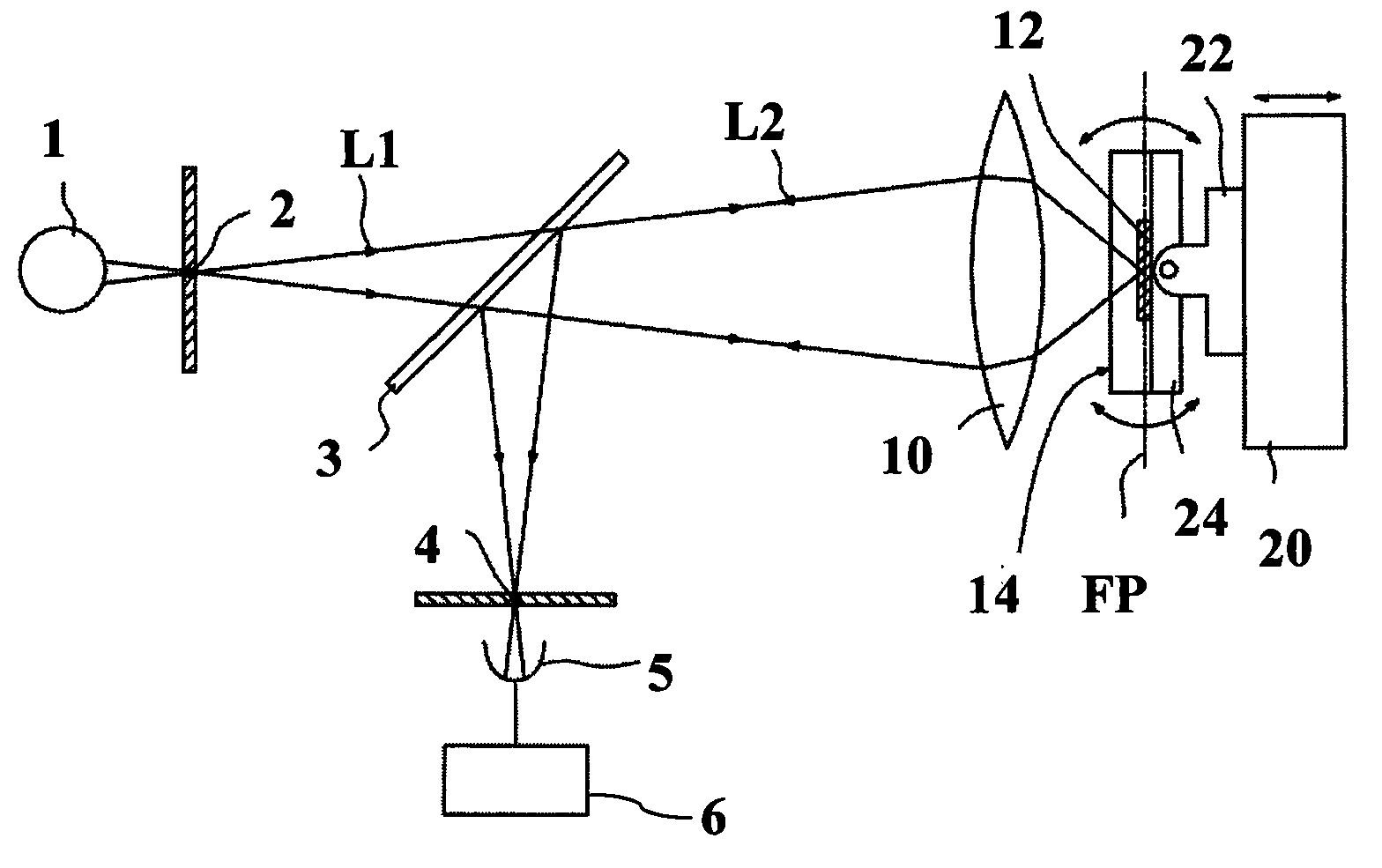
[0045]FIG. 4 is a schematic illustration showing a microscopy system according to the invention. Referring to FIG. 4, the microscopy system of this embodiment further includes a movable stage 20 for supporting the stage 14. The movable stage 20 is configured to be movable along the extending direction 16. Consequently, the stage 14 needs not to have to be movable.

[0046]FIG. 5 shows an example of a revolvable stage according to the invention. In the first and second embodiments, the stage 14 may include a base 22 and a revolvable sample holder 24. The revolvable sample holder 24 for supporting the sample 12 is rotatably mounted on the base 22 through a pivot 23. For example, the revolvable sample holder 24 is a flat plate.

[0047]FIG. 6 shows another example of the revolvable stage according to the invention. Referring to FIG. 6, the stage 14 further includes a positioning mechanism 30 for positioning an observation angle of the revolvable sample holder 24 in a stepwise manner. In this...


PUM


Abstract

A microscopy system includes an image focusing module, a stage for supporting a sample, image collection unit for collecting sliced images of the sample acquired by the image focusing module, and an image fusion unit for fusing sliced images of the sample acquired from different observation angles. The stage supports the sample and is configured to be revolvable around a rotational axis which is substantially perpendicular to an extending direction from the sample to the image focusing module so that enabling the image focusing module to acquire sliced images of the sample from different observation angles. The image fusion unit is used for remapping the sliced images acquired from different observation angles into a reference coordinate system, converting anisotropic voxels resolution of the sliced images to isotropic resolution, and fusing the sliced images into a final image.

Description

[0001]This application is a Continuation-In-Part of application Ser. No. 12 / 336,306, filed Dec. 16, 2008.FIELD OF THE INVENTION[0002]The invention relates in general to a microscopy system, and more particularly to a microscopy system having a revolvable stage.BACKGROUND OF THE INVENTION[0003]Confocal laser scanning microscopy (CLSM or LSCM) is a valuable tool for obtaining high resolution images and 3-D reconstructions by using a spatial pinhole to eliminate out-of-focus light or flare. This technology permits one to obtain images of various Z-axis planes (Z-stacks) of the sample. The detected light originating from an illuminated volume element within the specimen represents one pixel in the resulting image. As the laser scans over the plane of interest, a whole image is obtained pixel by pixel and line by line. The beam is scanned across the sample in the horizontal plane using one or more (servo-controlled) oscillating mirrors. Information can be collected from different focal p...

Claims


Application Information

Patent Timeline
Patent Type & Authority Applications(United States)
IPC IPC(8): H04N7/18G02B21/26G02B21/36
CPCG02B21/26G02B21/006
Inventor CHIANG, ANN-SHYNCHANG, HSIU-MINGCHEN, CHIA-HEFU, CHIEN-CHUNGHSIEH, CHANG-HUAIN
Owner NATIONAL TSING HUA UNIVERSITY
Why Eureka
Try Eureka