
Method and apparatus for relaying wireless traffic in a wireless network

a wireless network and wireless network technology, applied in the field of wireless network relay, can solve the problems of self-interference, major technical problem, and particularly harmful problem of control channel signal self-interferen

Inactive Publication Date: 2010-07-15
SAMSUNG ELECTRONICS CO LTD
View PDF6 Cites 20 Cited by
  • Summary
  • Abstract
  • Description
  • Claims
  • Application Information

AI Technical Summary

Benefits of technology

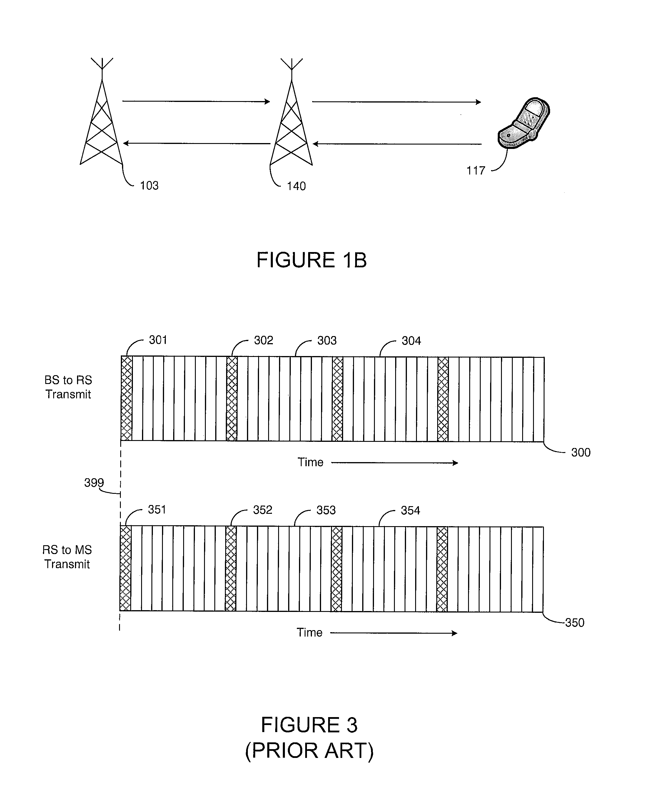
[0013]It is a further object of the present disclosure to provide a method of mitigating self-interference for use in a relay station configured to relay wireless traffic between a base station of a wireless network and a plurality of mobile stations. The method comprises the steps of: i) receiving from the base station incoming subframes of OFDM symbols, the incoming subframes comprising a first incoming common control channel subframe; 2) transmitting to the mobile stations outgoing subframes of OFDM symbols, the outgoing subframes comprising a first outgoing common control channel subframe; and 3) introducing a first timing offset between transmission of the first outgoing common control channel subframe and reception of the first incoming common control channel subframe, such that the first outgoing common control channel subframe is one of: i) transmitted prior to reception of the first incoming common control channel subframe by the first time offset; and ii) transmitted after reception of the first incoming common control channel subframe by the first time offset.

Problems solved by technology

However, self-interference is a major technical problem in relay operation.
Self-interference occurs when a relay station receives data from a base station while simultaneously transmitting to one or more mobile stations using the same time and frequency resources.
The self-interference problem is particularly harmful with respect to control channel signals, such as the synchronization (SYNC) channel, the primary broadcast channel (PBCH), or the like.
Self-interference is created because the PBCH subframe (or SYNC or other subframe) transmitted by the relay station carries a different payload that the PBCH subframe received by the relay station from the base station.

Method used


Image

  • Method and apparatus for relaying wireless traffic in a wireless network
  • Method and apparatus for relaying wireless traffic in a wireless network
  • Method and apparatus for relaying wireless traffic in a wireless network

Examples


Embodiment Construction

[0024]FIGS. 1 through 6, discussed herein, and the various embodiments used to describe the principles of the present disclosure in this patent document are by way of illustration only and should not be construed in any way to limit the scope of the disclosure. Those skilled in the art will understand that the principles of the present disclosure may be implemented in any suitably arranged wireless network.

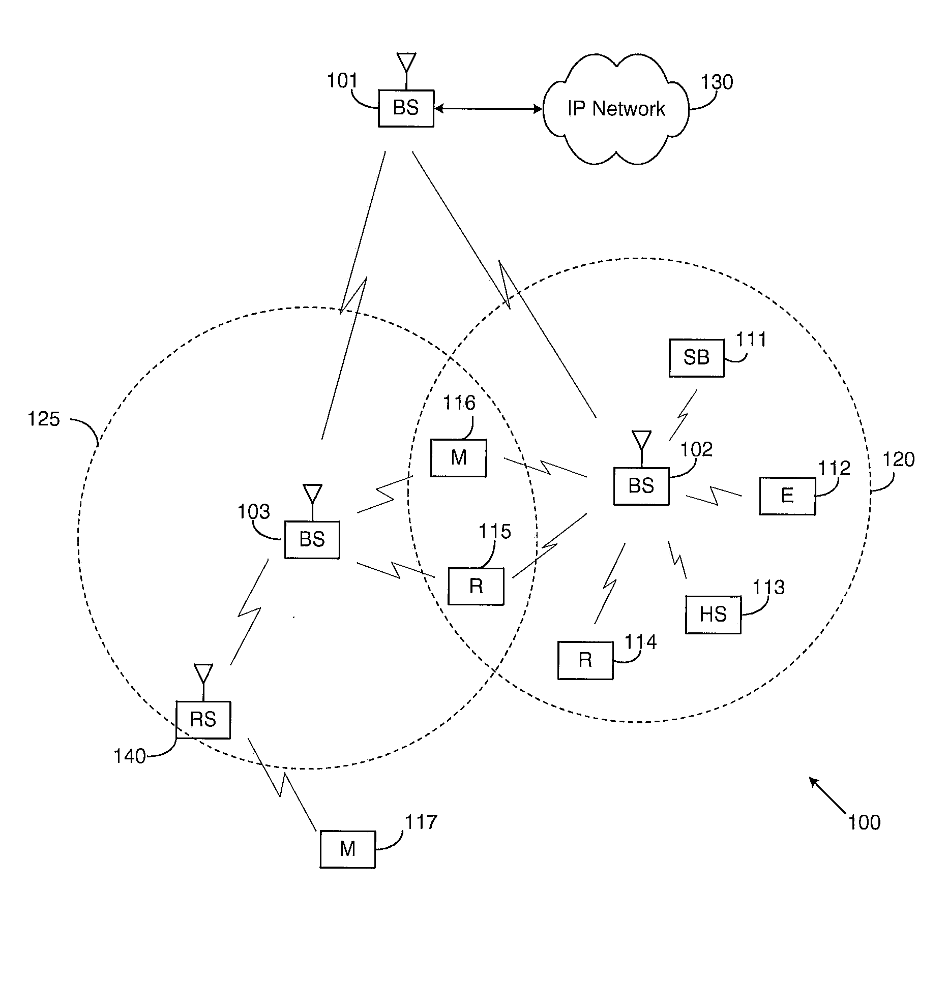
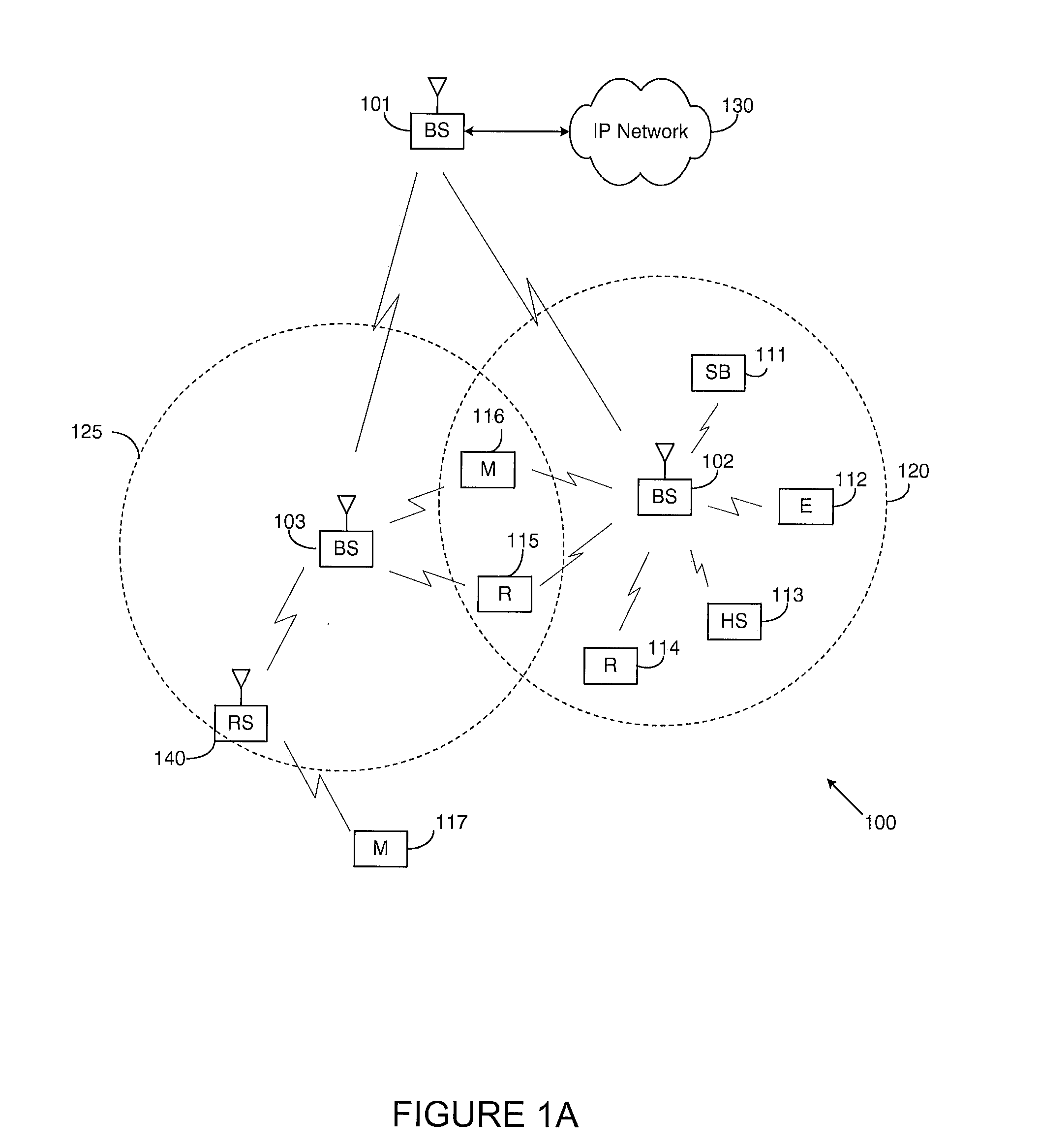
[0025]FIG. 1 illustrates exemplary wireless network 100 that is suitable for operating a relay station according to one embodiment of the present disclosure. In the illustrated embodiment, wireless network 100 includes base station (BS) 101, base station (BS) 102, and base station (BS) 103. Base station 101 communicates with base station 102 and base station 103. Base station 101 also communicates with Internet protocol (IP) network 130, such as the Internet, a proprietary IP network, or other data network.

[0026]Depending on the network type, other well-known terms may be used ins...


PUM


Abstract

A relay station to relay wireless traffic between a base station and mobile stations. The relay station receives incoming subframes of OFDM symbols and transmits outgoing subframes of OFDM symbols. The relay station comprises a timing offset controller configured to control the transmission of a first outgoing subframe with respect to reception of a first incoming subframe, such that the first outgoing subframe either leads or lags the reception of the first incoming subframe by a first time offset. The first time offset is equal to at least one OFDM symbol.

Description

CROSS-REFERENCE TO RELATED APPLICATION(S) AND CLAIM OF PRIORITY[0001]The present application is related to U.S. Provisional Patent Application No. 61 / 204,693, filed Jan. 9, 2009, entitled “METHOD OF RELAY OPERATION IN WIRELESS COMMUNICATIONS SYSTEMS”. Provisional Patent Application No. 61 / 204,693 is assigned to the assignee of the present application and is hereby incorporated by reference into the present application as if fully set forth herein. The present application hereby claims priority under 35 U.S.C. §119(e) to U.S. Provisional Patent Application No. 61 / 204,693.TECHNICAL FIELD OF THE INVENTION[0002]The present application relates generally to wireless communications systems and, more specifically, to a wireless network relay.BACKGROUND OF THE INVENTION[0003]The 3GPP LTE (Long Term Evolution) standard is the last stage in the realization of true 4th generation (4G) of mobile telephone networks. Most major mobile carriers in the United States and several worldwide carriers ha...

Claims


Application Information

Patent Timeline
IPC IPC(8): H04B3/36
CPCH04B7/15564H04L27/2655H04B7/2606
Inventor ZHANG, JIANZHONG
Owner SAMSUNG ELECTRONICS CO LTD
Learn More