Turbine blade assembly

a technology of turbine blades and assembly parts, which is applied in the direction of blade accessories, waterborne vessels, machines/engines, etc., can solve the problems of loss of efficiency, inability to introduce seal strips using the conventional sequential build methodology, and inability to heat disc rims. to achieve the effect of convenient assembly and disassembly

Inactive Publication Date: 2010-07-15
SIEMENS AG
View PDF5 Cites 19 Cited by
  • Summary
  • Abstract
  • Description
  • Claims
  • Application Information

AI Technical Summary

Benefits of technology

[0017]The seals can be fitted from the downstream bladed disc face. This allows for an easier assembly and disassembly.
[0

Problems solved by technology

Seal strips are used between adjacent turbine blades to prevent the ingress of hot gasses into a root cavity which can cause undesired heating of the disc rim and loss of efficiency.
Where blades are assembled into the disc as a full ring (for interlocked designs or where differential platform/root and shroud skew angles are in evidence) seal strips cannot be introduced using the conventional sequential

Method used


Image

  • Turbine blade assembly
  • Turbine blade assembly
  • Turbine blade assembly

Examples


Embodiment Construction

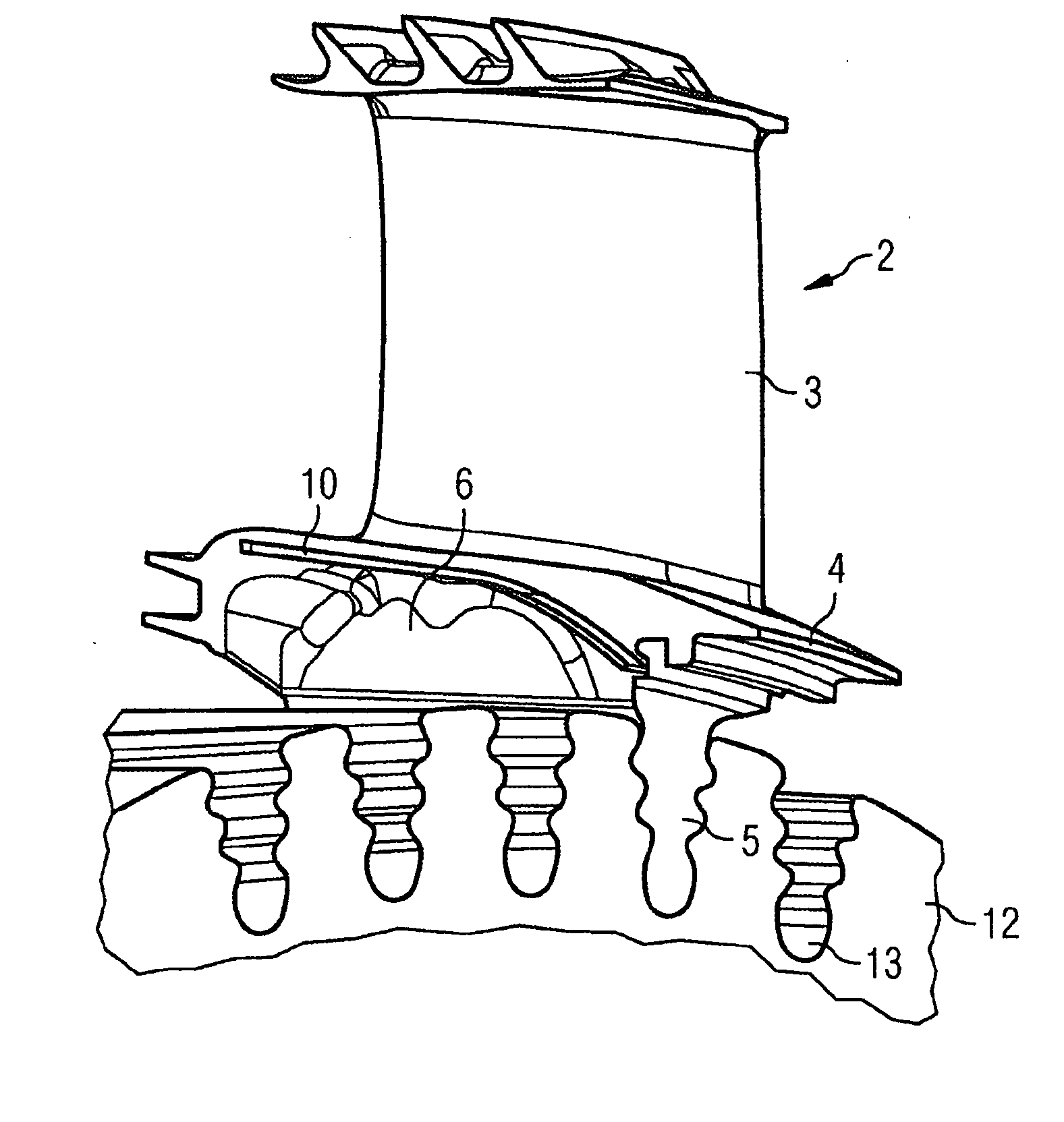
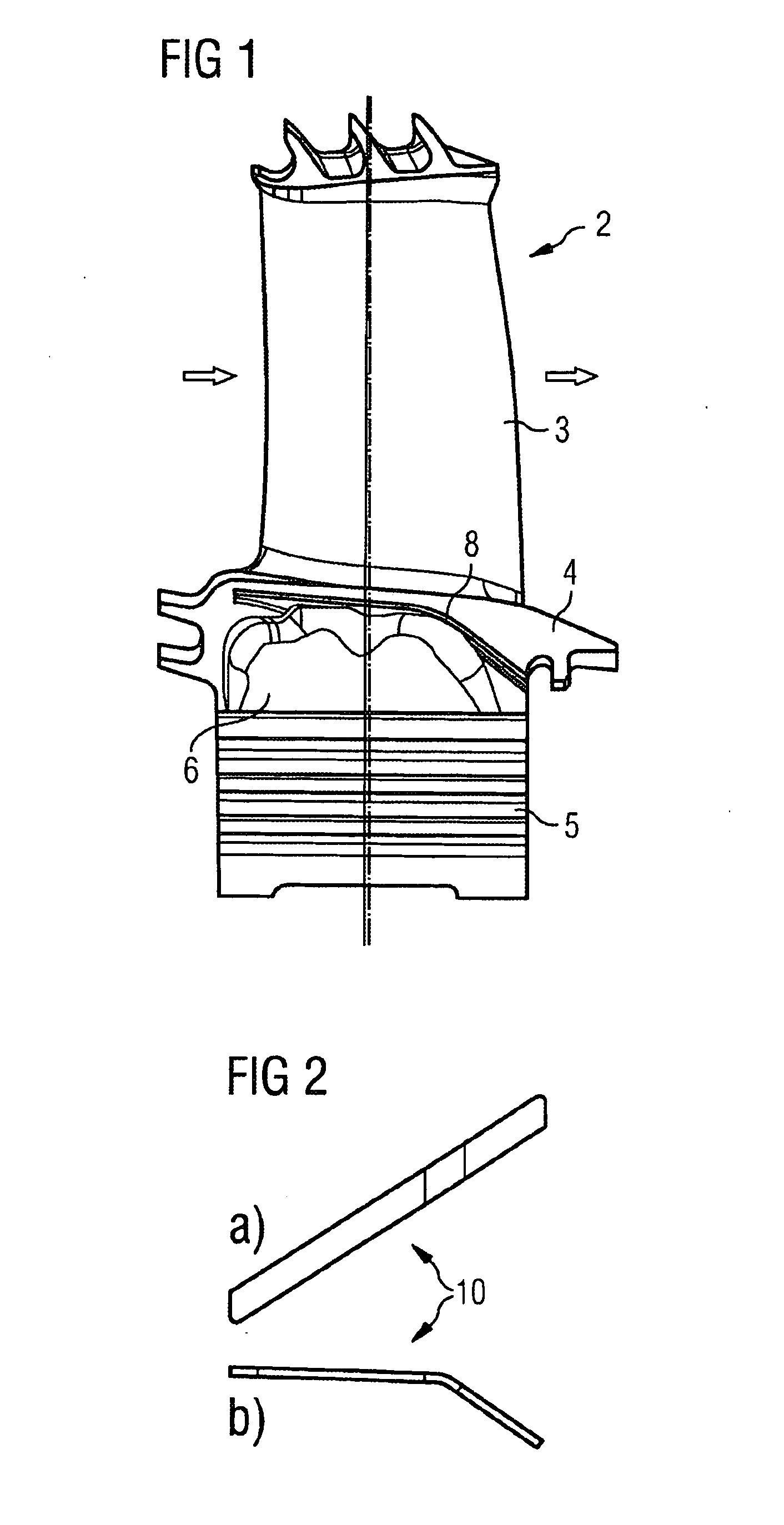
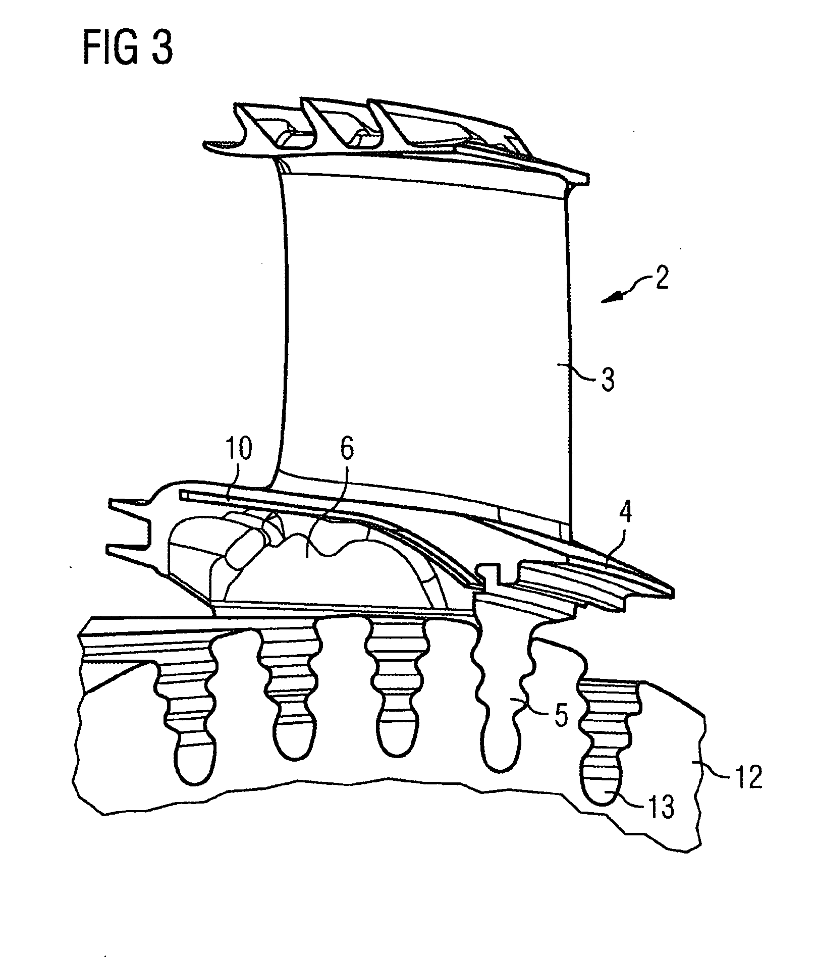
[0023]FIG. 1 shows a side view of a turbine blade 2 with a airfoil 3, a platform 4, a blade root 5, a root cavity 6 and a slot 8.

[0024]The platform 4 is placed at the bottom of the airfoil 3 and covers the root cavity 6 that is formed between the blade root 5 and the platform 4. A slot 8 is integrated into each side of the platform 4 running along the top of the root cavity 6. When assembled to a turbine disc 12 two slots 8 of two adjacent turbine blades 2 are in an opposed position to hold a seal strip 10 from two sides. The slots 8 are closed towards the upstream end for retention and open towards the downstream end of the turbine blade 2 for insertion. Each two opposed slots 8 are provided as guides and retentions of a seal strip 10.

[0025]The turbine blade 2 is used in a gas turbine where hot pressurized gas is guided towards turbine blades with airfoils that are fixed on a rotor to move the turbine blades and thus drive the rotor to which the turbine blades are assembled in a ci...


PUM

PropertyMeasurementUnit
Flexibilityaaaaaaaaaa
Resilienceaaaaaaaaaa

Abstract

A turbine blade assembly, which can be used for a gas turbine is provided. The turbine blade assembly includes turbine blades with platforms, gaps between the platforms of adjacent turbine blades and seals. Each seal covers the gap between the platforms of two adjacent turbine blades wherein the platforms are provided with slots extending in the downstream flow direction. The turbine blades have root cavities, wherein the seal covers at least the whole length of the root cavities of two adjacent turbine blades. The seal is formed from a strip and the seal is placed in two opposed slots formed in each of the platforms of two adjacent turbine blades and open towards the respective downstream ends.

Description

CROSS REFERENCE TO RELATED APPLICATIONS[0001]This application is the US National Stage of International Application No. PCT / EP2007 / 059084, filed Aug. 31, 2007 and claims the benefit thereof. The International Application claims the benefits of European Patent Office application No. 06021770.0 EP filed Oct. 17, 2006, both of the applications are incorporated by reference herein in their entirety.BACKGROUND OF THE INVENTION[0002]The invention relates to a turbine blade assembly, in particular for a gas turbine and a method for assembling a turbine blade assembly.[0003]Seal strips are used between adjacent turbine blades to prevent the ingress of hot gasses into a root cavity which can cause undesired heating of the disc rim and loss of efficiency. Where blades are assembled into the disc as a full ring (for interlocked designs or where differential platform / root and shroud skew angles are in evidence) seal strips cannot be introduced using the conventional sequential build methodology...

Claims


Application Information

Patent Timeline
IPC IPC(8): F01D11/00
CPCF01D11/006Y10T29/49321F05D2300/501
Inventor CHARLTON, SCOTT
Owner SIEMENS AG
Why Eureka
Try Eureka