Switchable rotation drive device

Inactive Publication Date: 2010-07-15
HARMONIC INC
View PDF3 Cites 1049 Cited by
  • Summary
  • Abstract
  • Description
  • Claims
  • Application Information

AI Technical Summary

Benefits of technology

[0022]In the present invention, causing only the switching sleeve to slide allows the output shaft to be switched between high-speed rotation and low-spee

Problems solved by technology

Furthermore, since the entirety of the power train unit that has the planetary gear mechanism is made

Method used


Image

  • Switchable rotation drive device
  • Switchable rotation drive device
  • Switchable rotation drive device

Examples


embodiment 1

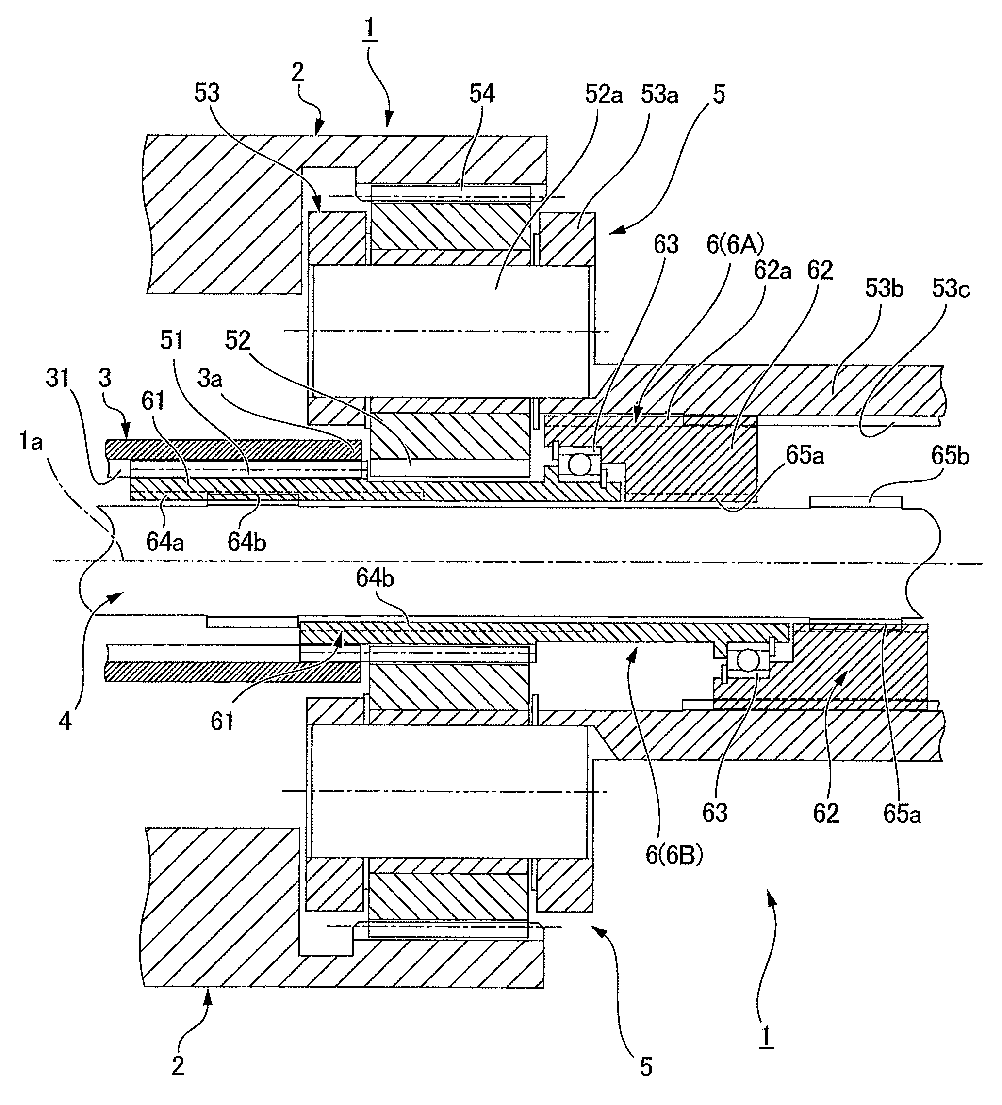
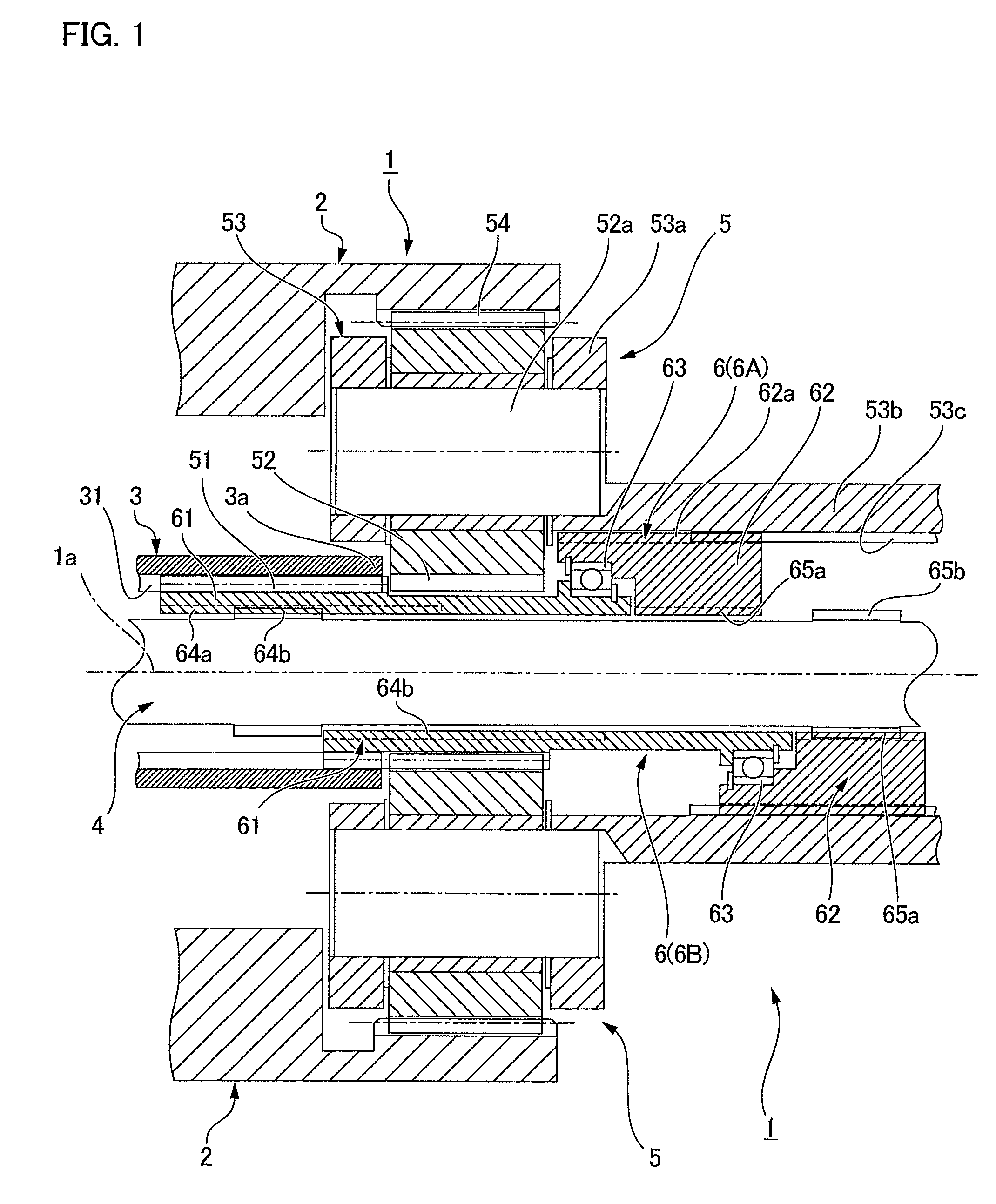
[0026]FIG. 1 is a schematic configuration diagram that primarily shows a switching device of a switchable rotating drive device according to an embodiment of the present invention. In the drawing a state in which a switching mechanism is in a position for high-speed mode is shown in the upper half part, and a state in which the switching mechanism is in a position for low-speed mode is shown in the lower half part.

[0027]A switchable rotation drive device 1 has a motor (not shown in the drawing) provided with a hollow rotor 3 that is incorporated in a cylindrical device housing 2; an output shaft 4 that rotatably extends through a hollow part of the hollow rotor 3 in a coaxial state; a planetary gear reduction mechanism 5 disposed on a part of the output shaft 4 that protrudes rearward from a rear end 3a of the hollow rotor 3; and a switching mechanism 6 for switching the output shaft 4 to a state for high-speed rotation or low-speed rotation,

[0028]For example, when used in a spindle...

embodiment 2

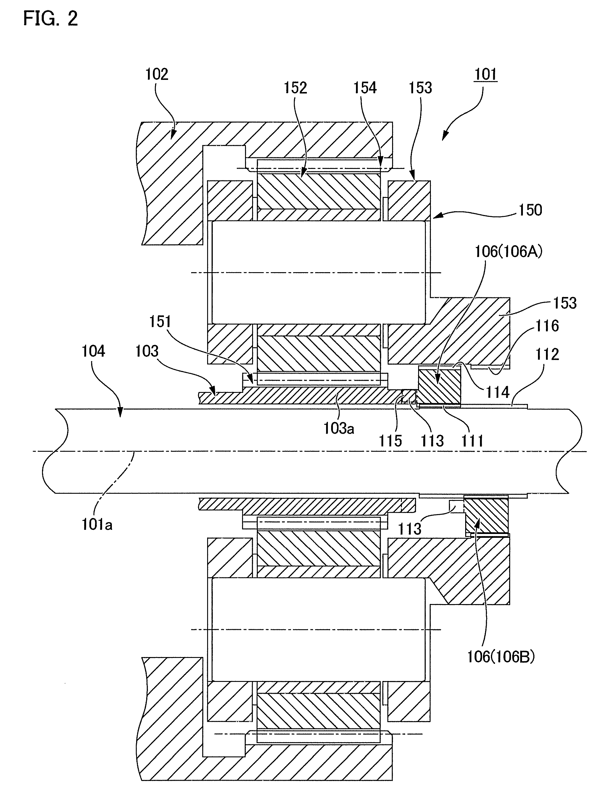
[0037]FIG. 2 is a schematic configuration diagram that shows a switching mechanism in a switchable rotating drive device according to a second embodiment in which the present invention is applied. In the diagram, a state in which a switch mechanism is in a position for high-speed mode is shown in the upper half part, and a state in which the switch mechanism is in a position for low-speed mode is shown in the lower half part.

[0038]The entire configuration of a switchable rotation drive device 101 is similar to the first embodiment. [The switchable rotation drive device 101] has a motor (not shown in the diagram) provided with a hollow rotor 103 that is incorporated in a device housing 102; an output shaft 104 that extends and rotatably passes through a hollow part of the hollow rotor 103 in a coaxial state; a planetary gear reduction mechanism 150 disposed on a part that protrudes rearward from a rear end 103a of the hollow rotor 103 in the output shaft 104; and a switching sleeve 1...


PUM


Abstract

A switchable rotation drive device has a switching mechanism wherein a first connecting sleeve that always rotates integrally with a motor hollow rotor, and a second connecting sleeve that always rotates integrally with a planetary carrier of a planetary gear reduction mechanism are connected via a bearing in a relatively rotatable state, and the first connecting sleeve is formed with a sun gear. By sliding the switching mechanism, the output shaft can be switched between high-speed rotation and low-speed rotation. In comparison to a case in which the entirety of the planetary gear reduction mechanism is made to slide, the sliding region may be smaller, and the required space needed to allow sliding may also be smaller. Therefore, it is advantageous to reduce the size of the device and make it more compact.

Description

TECHNICAL FIELD[0001]The present invention relates to a switchable rotation drive device that is capable of switching between a high-speed rotating mode, in which an output shaft is directly connected to a motor; and a low-speed rotating mode in which the output shaft is connected to the motor via a reduction mechanism.BACKGROUND ART[0002]A reducer is used to reduce the rotation of an output shaft and increase torque; however, when it is desired that the output shaft is made to rotate at a high speed and the speed of movement of a driven object is to be increased, or in other circumstances, a switching mechanism is used, and the rotation of the motor is transmitted directly to the output shaft. A spindle driving device for a machine tool, as disclosed in patent document 1, is known as a rotating drive device provided with a switching mechanism.[0003]According to the spindle driving device for a machine tool as disclosed in patent document 1, a power train unit having a planetary gea...

Claims


Application Information

Patent Timeline
IPC IPC(8): F16H3/44B23Q5/14
CPCB23Q5/14B23Q2005/005F16H3/54B23Q5/04B23Q5/12
Inventor SHIROKOSHI, NORIO
Owner HARMONIC INC
Why Eureka
Try Eureka