Ultrasound catheter with rotatable transducer

a transducer and ultrasonic technology, applied in the field of ultrasonic catheters, can solve the problem of not being able to view the area in front of the catheter assembly

Active Publication Date: 2010-07-15
VOLCANO CORP
View PDF11 Cites 71 Cited by
  • Summary
  • Abstract
  • Description
  • Claims
  • Application Information

AI Technical Summary

Benefits of technology

[0007]An ultrasound catheter assembly having a rotatable transducer assembly is disclosed. The ultrasound catheter assembly includes an elongate flexible shaft having a lumen and a proximal end and a distal end. A collar is coupled to the distal end. The transducer assembly, comprising a transducer element and transducer housing, is rotatably mounted within the collar. The catheter assembly further includes a drive member that traverses the length of the flexible shaft and engages the transducer housing. Rotation of the drive member in a first direction causes the transducer housing to rotate in an oscillatory fashion in a second direction.

Problems solved by technology

However, such arrangements typically provide a side looking view and it is not possible to view the area in front of the catheter assembly.
In addition, implementations that utilize an array typically require additional circuitry to control multiple transducer elements.

Method used


Image

  • Ultrasound catheter with rotatable transducer
  • Ultrasound catheter with rotatable transducer
  • Ultrasound catheter with rotatable transducer

Examples


Embodiment Construction

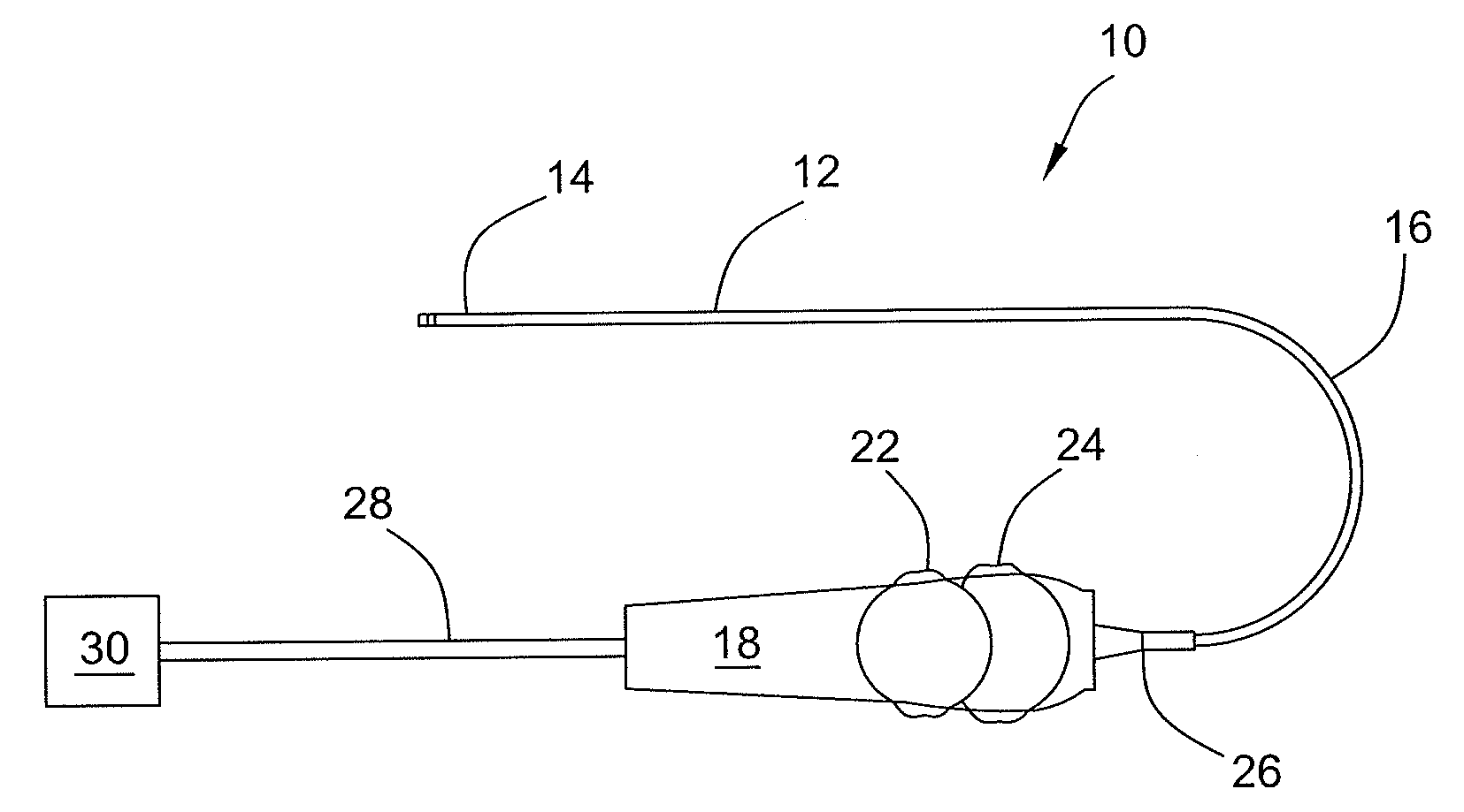
[0015]The following embodiments are related to an ultrasound catheter assembly 10. For the purpose of illustration, the ultrasound catheter assembly 10 is described in the context of an ultrasound catheter system for use as an intracardiac echocardiography (ICE) catheter or an intravascular ultrasound (IVUS) catheter. However, it will be understood that other applications of the disclosed catheter assembly are contemplated for alternative embodiments. For example, the disclosed ultrasound catheter can be used in any application where it is desirable to image a chamber or cavity that is accessible via a lumen.

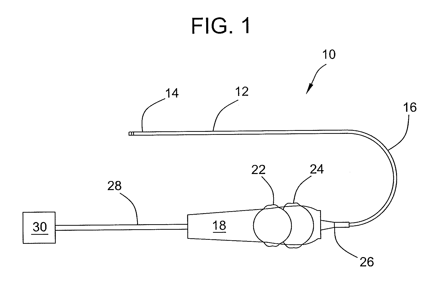
[0016]FIG. 1 illustratively depicts an embodiment of the catheter assembly 10 including a catheter shaft 12. The catheter shaft 12 is a generally flexible elongate member having a distal segment 14 and a proximal segment 16. The proximal segment 16 is optionally attached to a handle 18. The handle 18 may include a motor assembly arranged to rotate a drive member and / or incorpora...


PUM


Abstract

An ultrasound catheter assembly having a rotatable transducer assembly is disclosed. The ultrasound catheter assembly includes an elongate flexible shaft having a lumen and a proximal end and a distal end. The catheter assembly further includes a drive member that engages the transducer assembly at a distal end of the catheter. Rotation of the drive member in a first direction causes the transducer assembly to rotate in an oscillatory fashion in a second direction.

Description

FIELD OF THE INVENTION[0001]The present invention generally relates to ultrasound catheters. More specifically, the present invention pertains to an ultrasound catheter having a rotatable transducer element that provides a forward looking view in intracardiac or intravascular diagnostics.BACKGROUND OF THE INVENTION[0002]The development of new medical technologies and equipment has provided an increasing number of options available to doctors for the diagnosis and treatment of cardiovascular diseases. For example, ultrasound imaging technologies have enabled doctors to create and view a variety of images generated by one or more sensors inserted within a vasculature.[0003]One ultrasound imaging technology that has been employed is intravascular ultrasound (IVUS). In IVUS imaging systems, an ultrasonic transducer assembly is attached to a distal end of a catheter. The catheter is carefully maneuvered through a patient's body, usually over a guide wire, to an area of interest such as w...

Claims


Application Information

Patent Timeline
Patent Type & Authority Applications(United States)
IPC IPC(8): A61B8/00
CPCA61B8/12A61B8/445A61B8/4461A61B8/4483
Inventor DAVIES, STEPHEN CHARLESHOSSACK, NORMAN H.
Owner VOLCANO CORP
Why Eureka
Try Eureka