Reciprocating solar engine with attached solar windows

Inactive Publication Date: 2010-07-22
KENERGY SCI
View PDF12 Cites 4 Cited by
  • Summary
  • Abstract
  • Description
  • Claims
  • Application Information

AI Technical Summary

Benefits of technology

[0016]In some preferred embodiments of the present invention reciprocal solar engine, the roof is a rectangular shaped roof from a top view. Any other shape could be employed, but for most practical applications, the shape of an open wall or housing similar to a home, shed, or building may be aesthetically and functionally easier to design and to view. (One of the advantages of the present invention over roof mounted solar panels or very tall wind turbines, is that they can be placed in a yard or field or lot and externally appear as a normal structure or br surrounded by trees or other attractive cover. Unlike wind turbines, the objectional height and noise issues are eliminated and unlike roof-mounted solar panels, roof support and appearance issues are eliminated.)

Problems solved by technology

U.S. Pat. No. 4,132,223 to E. Garland Reddell describes a pivotally mounted solar energy collector is maintained oriented towards the sun by creating a continuing imbalance of the collector about its pivotal axis resulting in pivotal movement of the collector to track the sun.
The imbalance is achieved by regulating the flow of a pumped fluid from a container located at one side of the collector to a container located at another side of the collector.

Method used


Image

  • Reciprocating solar engine with attached solar windows
  • Reciprocating solar engine with attached solar windows
  • Reciprocating solar engine with attached solar windows

Examples


Embodiment Construction

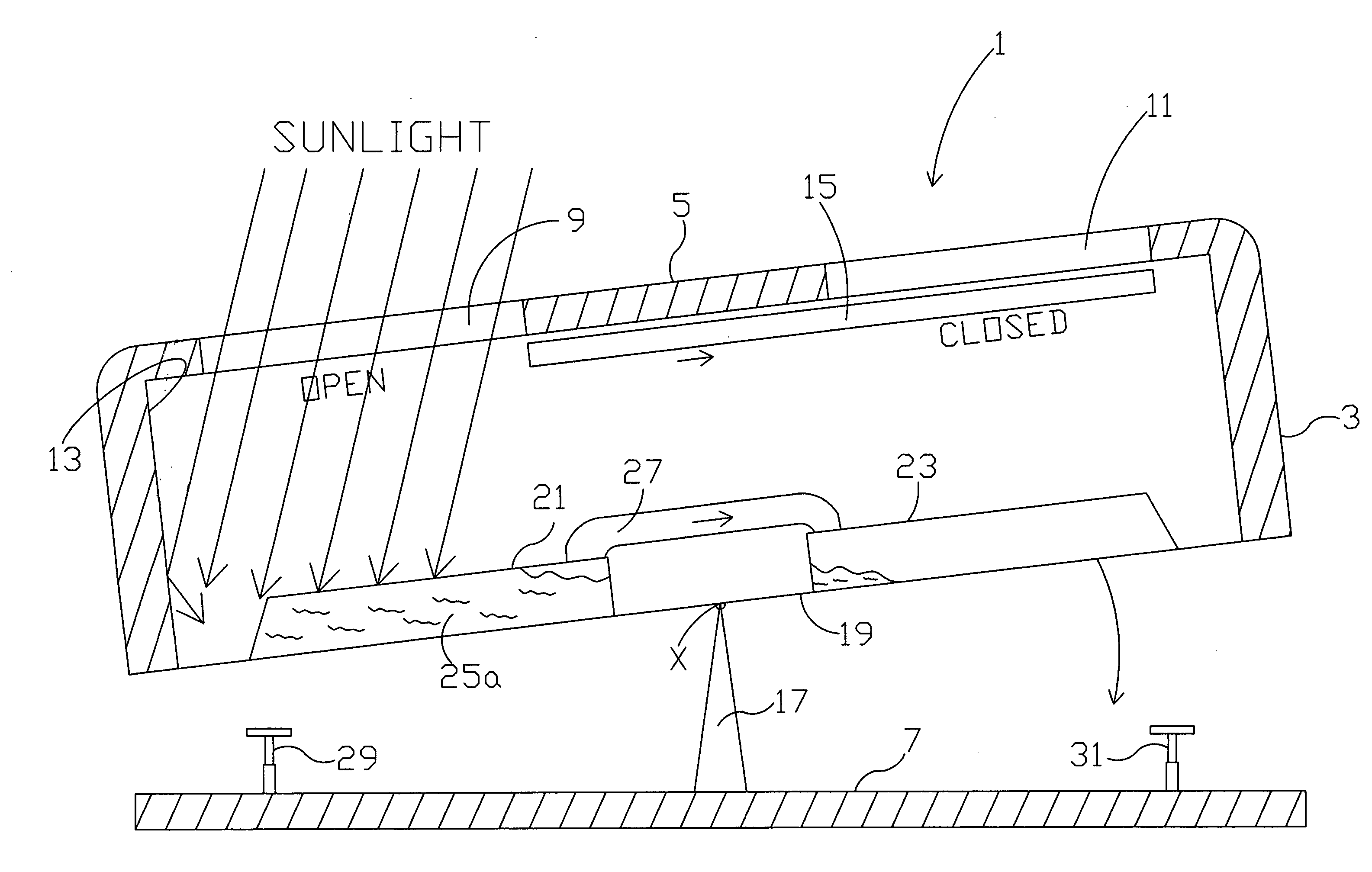
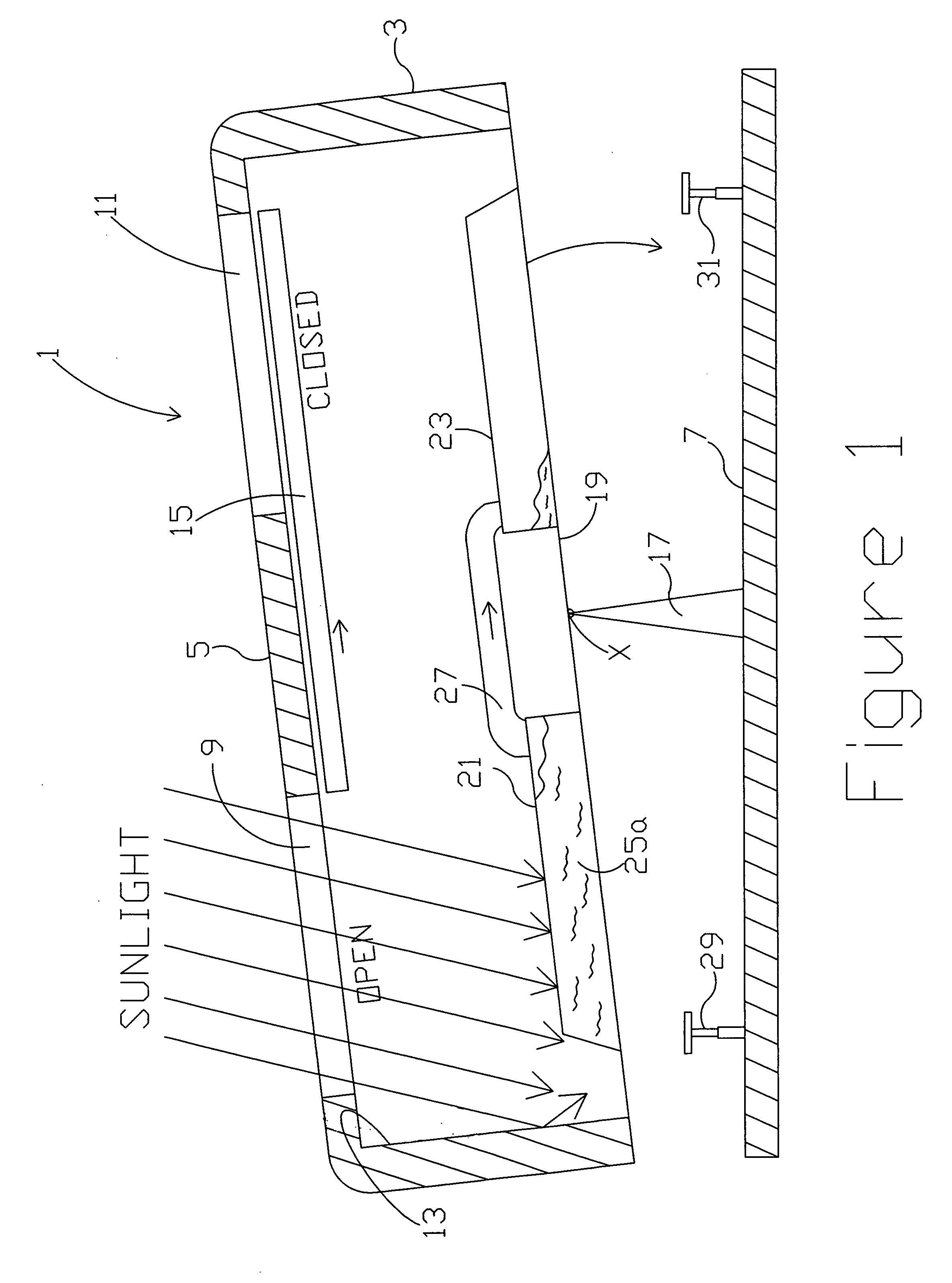
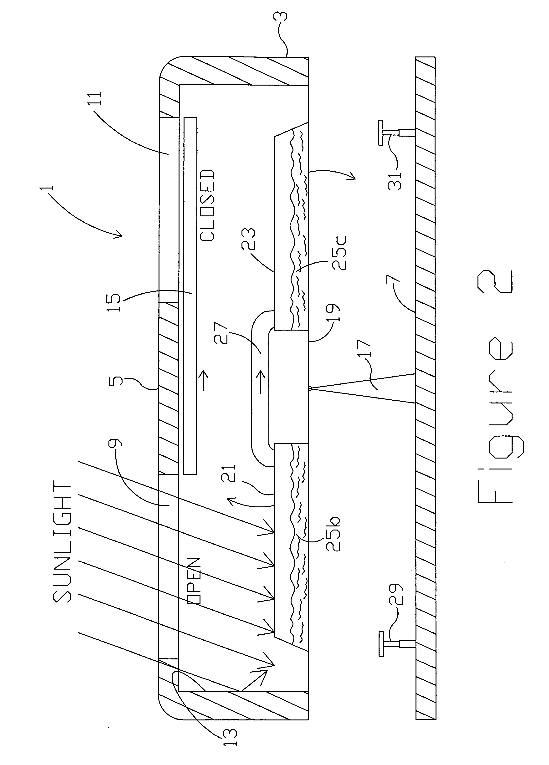
[0036]The present invention reciprocating solar engine is based on material transfer back and forth across a fulcrum utilizing solar energy to cause the material transfer. The material transfer occurs when solar energy heats a liquid in a container to cause some vaporization of the liquid, the vaporized liquid (gas) then condenses to liquid in a container on the opposite side of the fulcrum, and the weight shift causes mass to rotate about the fulcrum. The present invention reciprocating solar engine may be used as a driving force for any purpose, e.g. turning a turbine to generate electricity, operating a pump to move liquid such as water, operating reciprocating pistons, or turning a production wheel.

[0037]FIG. 1 is a side cut view of a preferred embodiment of a present invention reciprocating solar engine 1. Solar engine 1 includes a base 7, with a central fulcrum support 17 thereon. The support 17 is represented as a triangular support, but could be any form of fulcrum support m...


PUM


Abstract

A reciprocating solar engine includes a) a seesawing platform having a central fulcrum support upon which the platform is moveably positioned to reciprocally rotate through a predetermined arc b) a first solar heat-receiving closed container located on the platform on one side of the support and a second solar heat-receiving closed container located on the platform on a second side of the support; c) a connecting tube connecting the first container and the second container; d) a fluid contained within at least one of the first and the second container, the fluid being evaporable from solar heat and condensable from shading from solar heat; e) a roof above and connected to the platform, having at least one window of which is located above the first container and at least one window of above the second container; f) shuttering devices connected to the roof and movable so that one window is closed while the other is open and vice versa; and, g) shutter device controls functionally connected to the shutter device and the platform such that the shutter device controls activate the shutter devices to a first rest position when the second solar heat-receiving closed container is at its arc base, and to the second rest position when the first solar heat-receiving closed container is at its arc base.

Description

REFERENCE TO RELATED APPLICATIONS[0001]This application is a continuation-in-part of copending U.S. patent application Ser. No. (to be issued), Docket Number KDC-105A, filed on Jan. 5, 2009 by the inventor herein, entitled “Reciprocating Solar Engine”.BACKGROUND OF INVENTION[0002]a. Field of Invention[0003]The invention relates generally to a reciprocating solar engine that is based on material transfer back and forth across a fulcrum utilizing solar energy to cause the material transfer. The present invention reciprocating solar engine may be used as a driving force for any purpose, e.g. turning a turbine to generate electricity, operating a pump to move liquid such as water, operating reciprocating pistons, or turning a production wheel.[0004]b. Description of Related Art[0005]The following patents are representative of the field pertaining to the present invention:[0006]U.S. Pat. No. 4,476,854 to Stephen C. Baer describes an apparatus for tracking the sun which reorients itself i...

Claims


Application Information

Patent Timeline
IPC IPC(8): F03G6/06F03G6/00F24S50/20
CPCF03G6/00F03G6/06Y02E10/46Y02B10/30Y02B10/20F03G6/061
Inventor GLYNN, KENNETH P.
Owner KENERGY SCI
Why Eureka
Try Eureka