Power transmission device and vehicle having the same

a transmission device and transmission device technology, applied in the direction of clutches, mechanical equipment, gearing details, etc., can solve the problem of reducing the size of the mechanical oil pump in order to reduce the overall devi

Inactive Publication Date: 2010-07-22
AISIN AW CO LTD
View PDF1 Cites 28 Cited by
  • Summary
  • Abstract
  • Description
  • Claims
  • Application Information

AI Technical Summary

Benefits of technology

[0013]The vehicle of the present invention is installed with the power transmission device of the present invention of any of the modes described above. Therefore, effects achieved by the power transmission of the present invention, for...

Problems solved by technology

Therefore, reducing the size of the mechanical oil pump ...

Method used


Image

  • Power transmission device and vehicle having the same
  • Power transmission device and vehicle having the same
  • Power transmission device and vehicle having the same

Examples


Embodiment Construction

[0020]Next, an embodiment will be used to describe a best mode for carrying out the present invention.

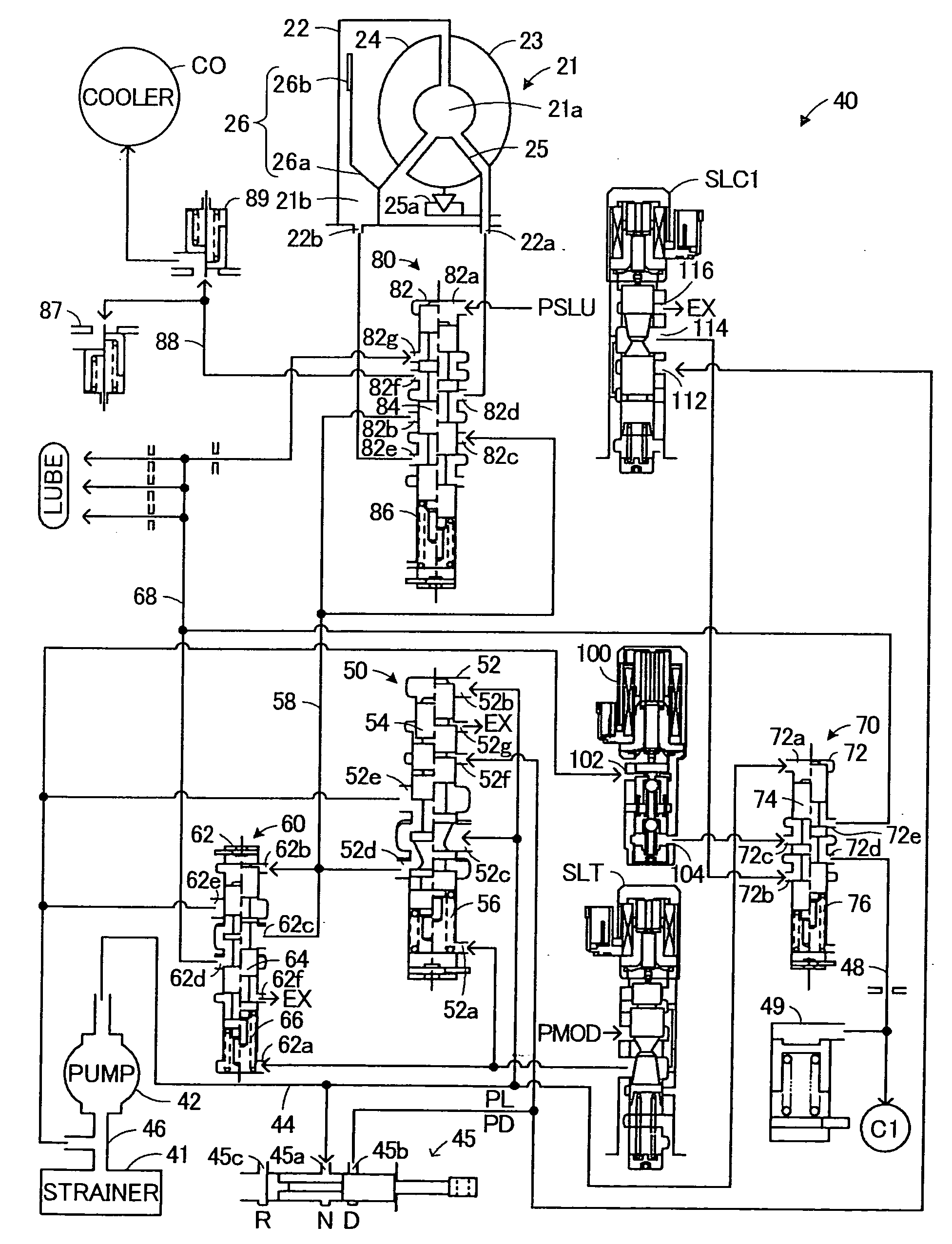
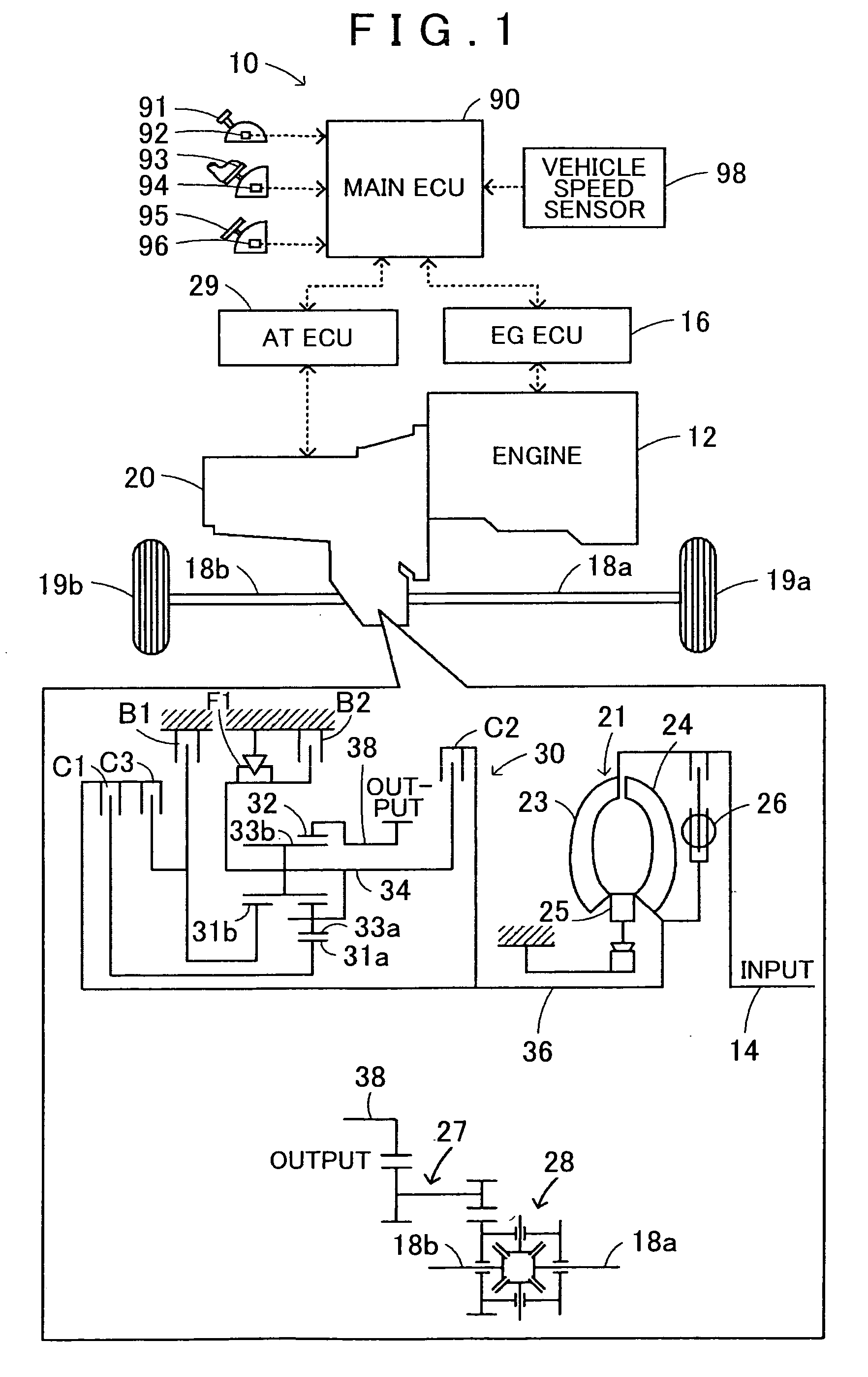
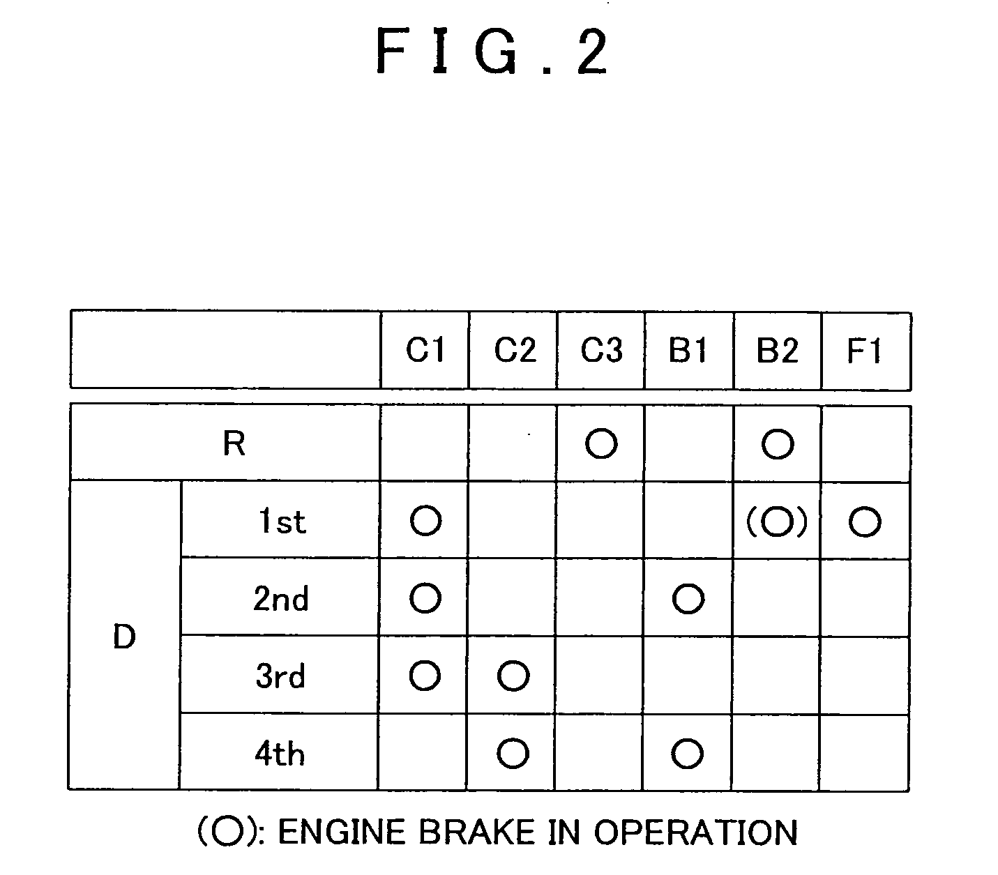
[0021]FIG. 1 is a structural diagram that shows an outline of the constitution of an automobile 10 incorporated with a power transmission device 20 serving as an embodiment of the present invention. FIG. 2 is an explanatory drawing that shows an operation chart of an automatic transmission 30 provided in the power transmission device 20. FIG. 3 is a structural diagram that shows an outline of the constitution of a hydraulic circuit 40 that drives the automatic transmission 30.

[0022]As FIG. 1 shows, the automobile 10 of the present embodiment includes an engine 12, an engine electronic control unit (engine ECU) 16, and a power transmission device 20. The engine 12 is an internal combustion engine that outputs power by explosive combustion of a hydrocarbon fuel such as gasoline or diesel. The engine ECU 16 is input with various signals such as an engine speed Ne from a rotation speed ...


PUM


Abstract

A power transmission device that includes a clutch that transmits power from a motor to an axle; a first pump that is driven by power from the motor to generate and output fluid pressure; a second pump that receives and is driven by a supply of electric power to generate and output fluid pressure; a pressure regulating valve that regulates a pressure of operation fluid output from the first pump, and delivers at least a portion of operation fluid discharged in connection with the pressure regulation to a lubrication target for use as lubricant; and a switching valve that switches between a first connection state and a second connection state.

Description

[0001]The disclosure of Japanese Patent Application No. 2009-008890 filed on Jan. 19, 2009 including the specification, drawings and abstract is incorporated herein by reference in its entirety.BACKGROUND[0002]The present invention relates to a power transmission device that is installed in a vehicle and provided with a clutch that transmits power from a motor to an axle side, and a vehicle having the power transmission device.[0003]This type of power transmission device conventionally has a first hydraulic pump (mechanical oil pump) that drives based on power from an engine; a manual shift valve that operates in association with a shift operation; a solenoid valve whose input port is connected to the first hydraulic pump through the manual shift valve; a selector valve that is interposed between oil passages and formed as a two-position electromagnetic valve (and includes a check valve), wherein at a first position the selector valve communicates with an oil passage that connects a...

Claims


Application Information

Patent Timeline
IPC IPC(8): F16D25/12F16H57/04F16H59/42F16H59/74F16H61/00F16H61/68F16H61/684F16H61/686
CPCF16H57/0441F16H61/0031Y10T477/69363F16H2312/14Y10T477/69395F16H2061/0037
Inventor SHIMIZU, TETSUYAKATO, KAZUHIKOFUKAYA, NAOYUKIISHIKAWA, KAZUNORI
Owner AISIN AW CO LTD
Why Eureka
Try Eureka