Cold block with integral beer tap

Inactive Publication Date: 2010-07-22
KIRSHBAUM BRUCE
View PDF29 Cites 8 Cited by
  • Summary
  • Abstract
  • Description
  • Claims
  • Application Information

AI Technical Summary

Problems solved by technology

This results in the tap remaining cooled so long as the glycol r

Method used


Image

  • Cold block with integral beer tap
  • Cold block with integral beer tap
  • Cold block with integral beer tap

Examples


Embodiment Construction

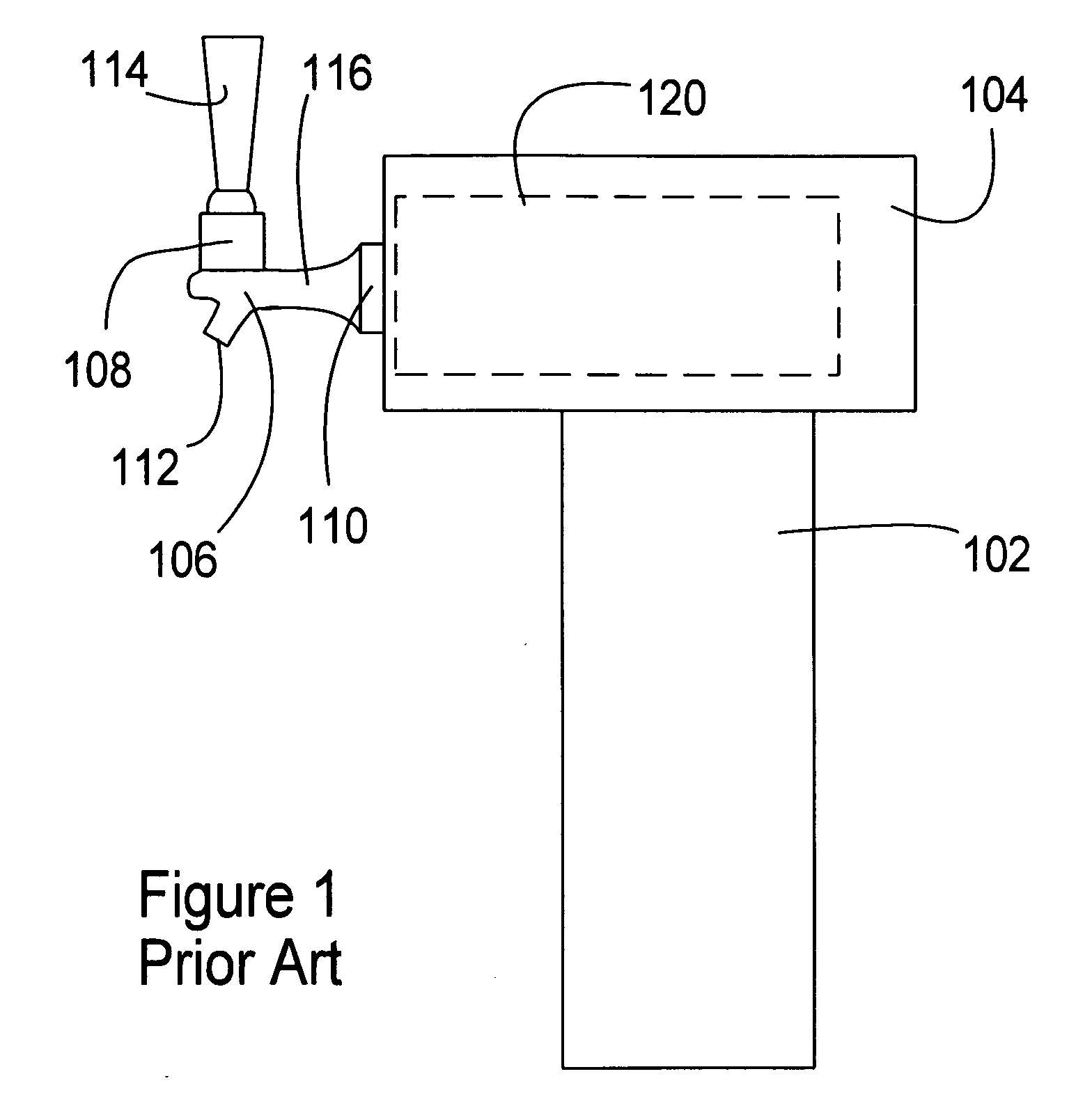
[0080]FIG. 1 is a partially transparent side view of a PRIOR ART beverage dispensing tower 102, such as has been on the market for many years, showing a typical cold block arrangement in a tower head 104.

[0081]Tower 102 typically projects upward above a work surface such as a bar or counter, with a drain or catch basin below. Tower top 104 projects out from tower 102, then tap 106 projects out from the top 104 further on extension section 116.

[0082]Valve section 108 meets handle 114 and allows motion of the handle 114 to actuate a valve within the tap 106. The operative valve seat may be within section 108 or elsewhere. In some prior art arrangements, the valve section 110 has the valve seat, so the valve actually seals at that location when the tap handle 114 is released. Valve section 110 seats directly into a cold block 120 within the head 104. This means that when the tap handle 114 is released and the valve closes, beverage within the tower head 104 is contained and cooled with...


PUM


Abstract

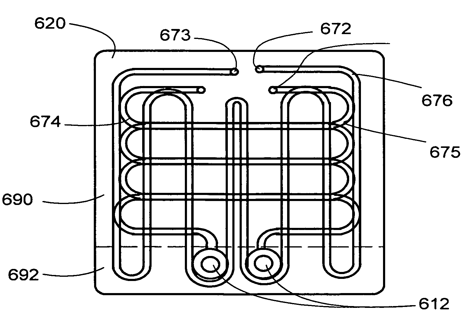
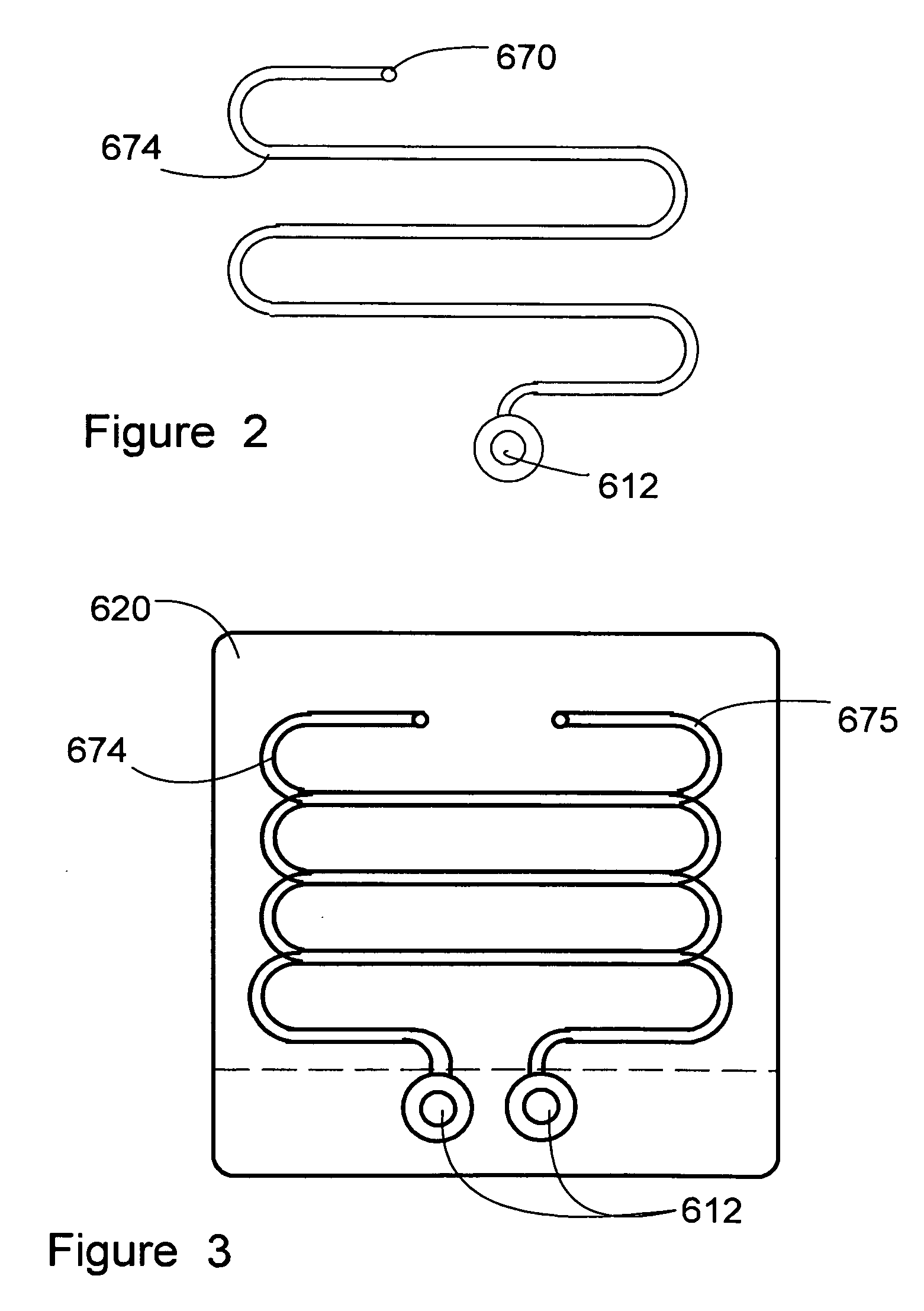
The present invention teaches a beverage tower of the type having a cold block with glycol recirculation, however, the traditional tap is actually built into the cold block, so as to keep the entire beer tap or other type of tap cold and maintain the beverages in a sanitary condition meeting health codes. The glycol lines within the cold block are then arranged so as to pass around the tap in the cold block, resulting in a tap which remains cooled so long as the glycol recirculation system keeps the block cold. Serpentine channels may be used so that the beverage passing through the beverage supply channels has a longer run in contact with the conductive material of the cold block and thus more opportunity to reject heat thereinto.

Description

COPYRIGHT NOTICE[0001]A portion of the disclosure of this patent document contains material which is subject to copyright protection. The copyright owner has no objection to the facsimile reproduction by anyone of the patent document or the patent disclosure, as it appears in the Patent and Trademark Office patent file or records, but otherwise reserves all copyright rights whatsoever. 37 CFR 1.71(d).CROSS-REFERENCE TO RELATED APPLICATIONS[0002]N / AFIELD OF THE INVENTION[0003]This invention relates generally to beverage, especially beer towers, and specifically to cold blocks in beverage towers.STATEMENT REGARDING FEDERALLY FUNDED RESEARCH[0004]This invention was not made under contract with an agency of the US Government, nor by any agency of the US Government.BACKGROUND OF THE INVENTION[0005]In beverage dispensing technology, it is imperative for both sanitary and regulatory reasons to maintain low temperatures in the product being dispensed. Different products have different regul...

Claims


Application Information

Patent Timeline
IPC IPC(8): B67D5/62
CPCB67D1/0862
Inventor ROBINSON, JON JOSEPH
Owner KIRSHBAUM BRUCE
Why Eureka
Try Eureka