Image compensation apparatus

a technology of compensation apparatus and compensation device, which is applied in the direction of two-way working system, color television details, television system, etc., can solve the problems of system ineffective compensation for the fast changing brightness and colours, and the effect of affecting the colour balance and/or brightness of the captured imag

Inactive Publication Date: 2010-07-22
SONY ESPANA
View PDF8 Cites 74 Cited by
  • Summary
  • Abstract
  • Description
  • Claims
  • Application Information

AI Technical Summary

Benefits of technology

[0009]According to the present invention, there is provided a method of image compensation for images captured by a video camera of a system including a video display and the video camera, the video camera capturing images of a scene in front of the display. The method includes analysing successive frames of data provided to the video display, the successive frames of data being for displaying respective successive display images, calculating the illumination effect of the successive display images on the scene in front of the video display, and applying image compensation to the successive images captured by the video camera so as to compensate for the effect of illumination by the video display of the scene in front of the video display.
[0022]In this way, the analyser can calculate an average brightness and / or an average colour for a particular display image. Using this average, the processor can calculate the illumination effect on the scene in front of the display device.

Problems solved by technology

The present application recognises for the first time a somewhat different problem, namely that the image produced by a display will necessarily illuminate the scene in front of the display and therefore have an effect on the image being captured by a camera, even if this camera is located in a more conventional manner alongside the display surface of the display.
This illumination may effect detrimentally the colour balance and / or brightness of the captured image.
Such systems are not effective in compensating for the fast changing brightness and colours resulting from illumination by a video display.

Method used


Image

  • Image compensation apparatus
  • Image compensation apparatus
  • Image compensation apparatus

Examples


Embodiment Construction

[0034]The invention will be more clearly understood from the following description given by way of example only with reference to the accompanying drawings.

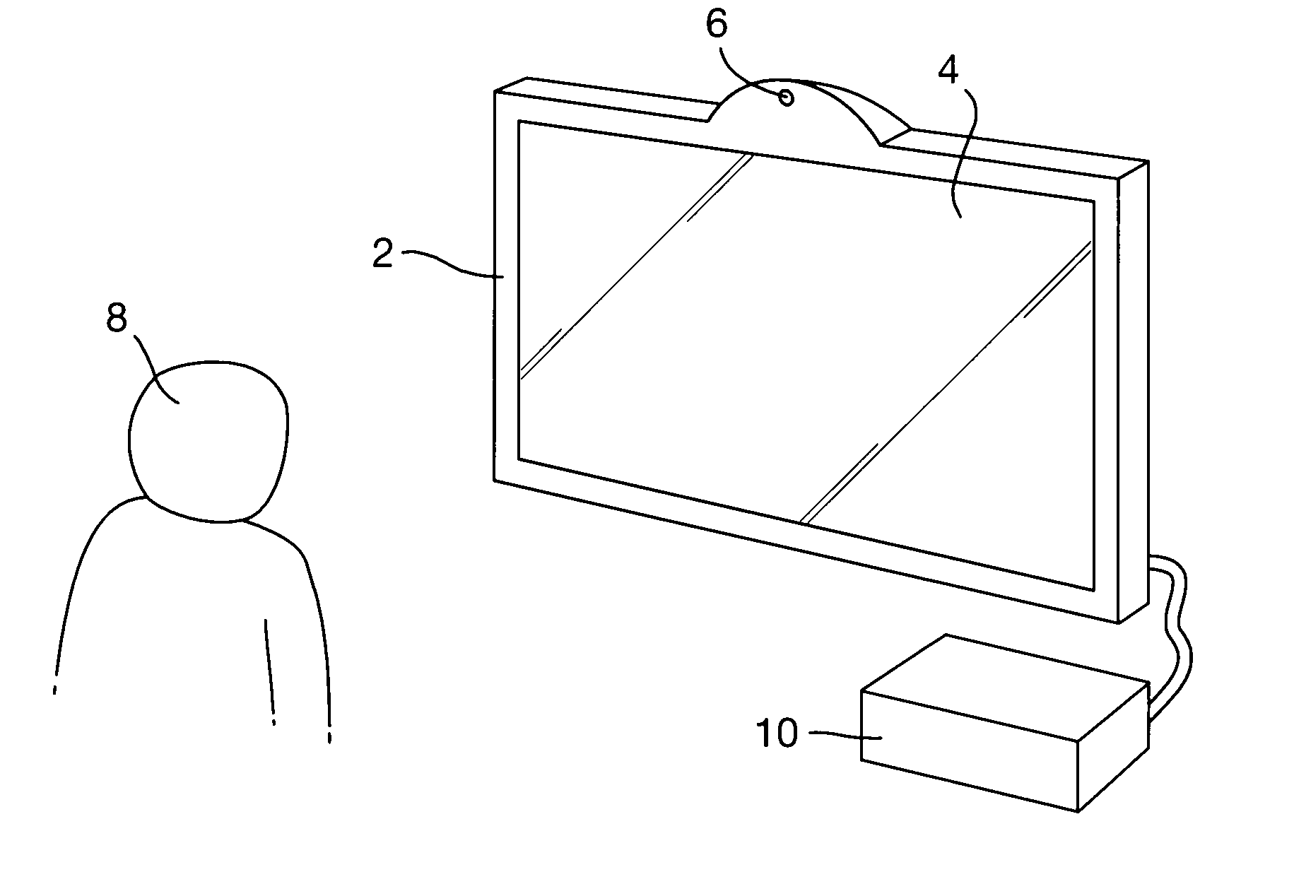
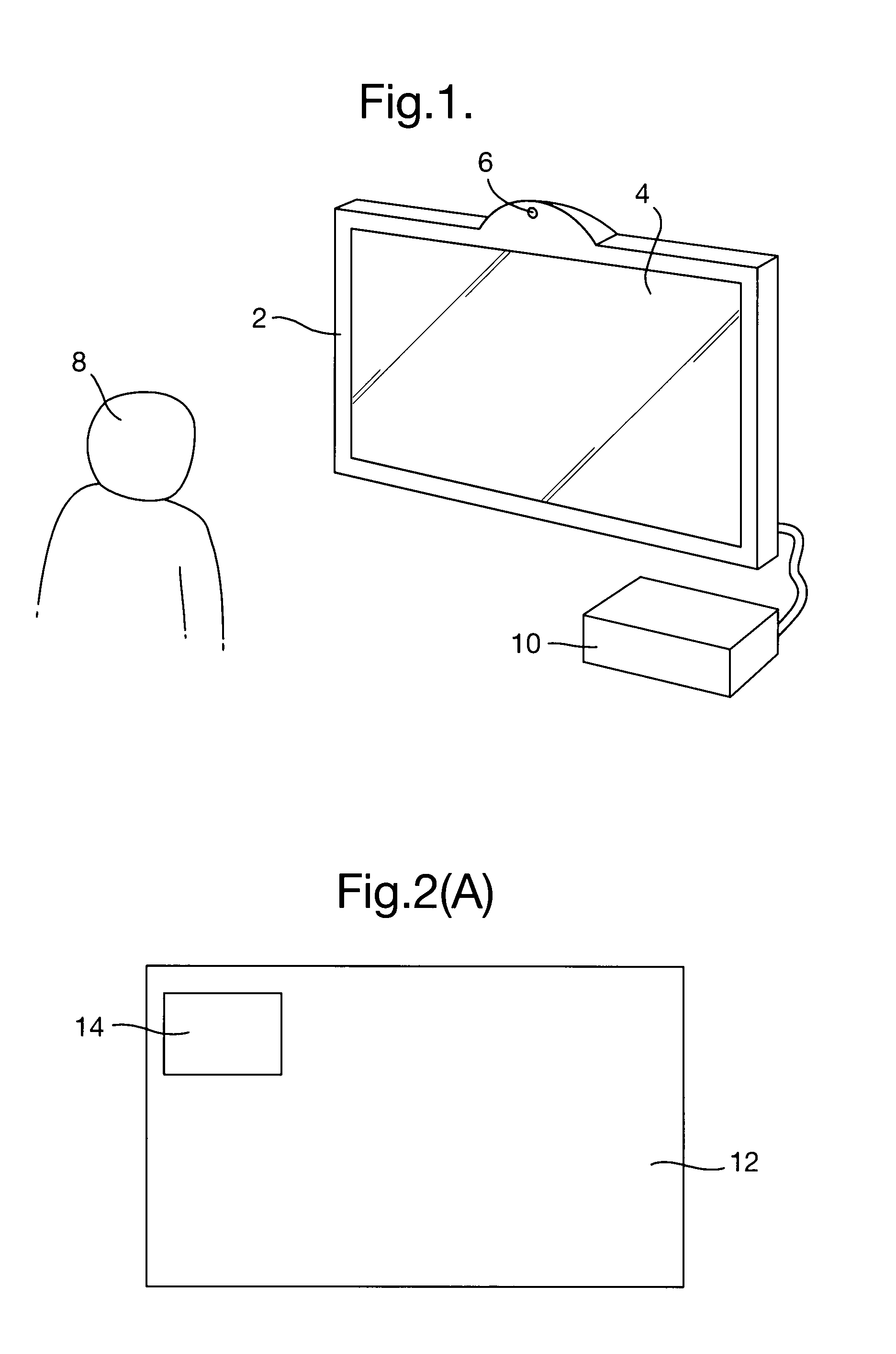
[0035]In order to improve and increase the functionality of a video display device, it is desirable to place a video camera alongside the video display.

[0036]FIG. 1 illustrates schematically a system having a video display 2 with a display surface 4 on which video display images may be displayed. Alongside the display surface 4, there is provided a video camera 6 which faces in the same direction as the display surface 4 so as to capture images of the scene in front of the video display 2. As illustrated, the scene in front of the video display 2 includes a viewer 8 or user of the system.

[0037]In the context of the present invention, the video display should be able to display a stream of successive images, for instance in the form of frames or fields. However, those images need not only produce video in a narrow sense but also a...


PUM


Abstract

An image compensation apparatus for use with a video display and a video camera, the video camera being arranged to capture images of a scene in front of the video display. The image compensation apparatus includes an analyser configured to analyse successive frames of data provided to the video display, the successive frames of data being for displaying respective successive display images, a processor configured to calculate the illumination effect of the successive display images on the scene in front of the video displays and a compensator configured to apply image compensation to the successive images captured by the video camera so as to compensate for the effect of illumination by the video display of the scene in front of the video display.

Description

CROSS-REFERENCE TO RELATED APPLICATIONS[0001]This application is based upon and claims the benefit of priority from British Application No. 0900867.3 filed 19 Jan. 2009, the entire contents of which are incorporated by reference.BACKGROUND OF THE INVENTION[0002]1. Field of the Invention[0003]The present invention relates to an image compensation apparatus and also a method of image compensation for images captured by a video camera of a system including a video display and the video camera.[0004]2. Description of the Related Art[0005]It is well known to provide video conferencing equipment in which a video camera is provided alongside a video display so as to capture images of the scene in front of the video display. With such a device, it is possible for a user to watch a video image displayed on the video display whilst a video image of that user is being captured by the camera for transmission to another remote user. The display may reproduce a video image of that other remote us...

Claims


Application Information

Patent Timeline
Patent Type & Authority Applications(United States)
IPC IPC(8): H04N5/228
CPCH04N5/23229H04N5/23293H04N7/147H04N7/15H04N9/735H04N23/80H04N23/63H04N23/88H04N23/70
Inventor MATSUBAYASHI, KEI
Owner SONY ESPANA
Why Eureka
Try Eureka