Lighting device, display device and television receiver

a technology of display device and light source, which is applied in the direction of lighting and heating equipment, television systems, instruments, etc., can solve problems such as uneven brightness

Inactive Publication Date: 2010-07-22
SHARP KK
View PDF10 Cites 6 Cited by
  • Summary
  • Abstract
  • Description
  • Claims
  • Application Information

AI Technical Summary

Benefits of technology

[0019]In view of this, the opening section is located directly below the linear light sources. According to the construction, the linear light source can be p

Problems solved by technology

If the illumination brightness differs excessively between the narrow-interval area and the wide-interval area, the entire distribution of illumination brig

Method used


Image

  • Lighting device, display device and television receiver
  • Lighting device, display device and television receiver
  • Lighting device, display device and television receiver

Examples


embodiment 1

[0035]An embodiment 1 according to the present invention will be explained with reference to FIGS. 1 to 5.

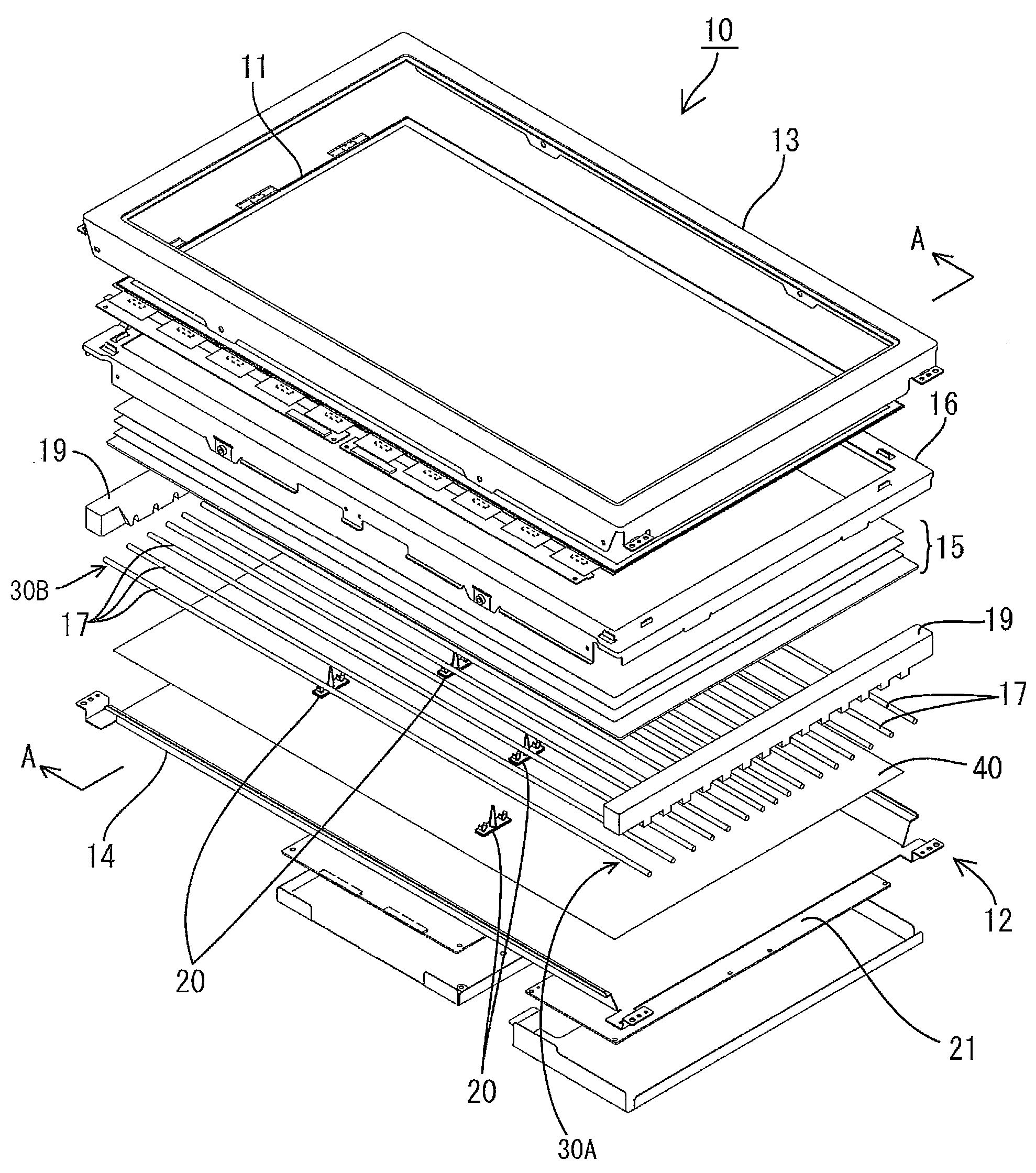
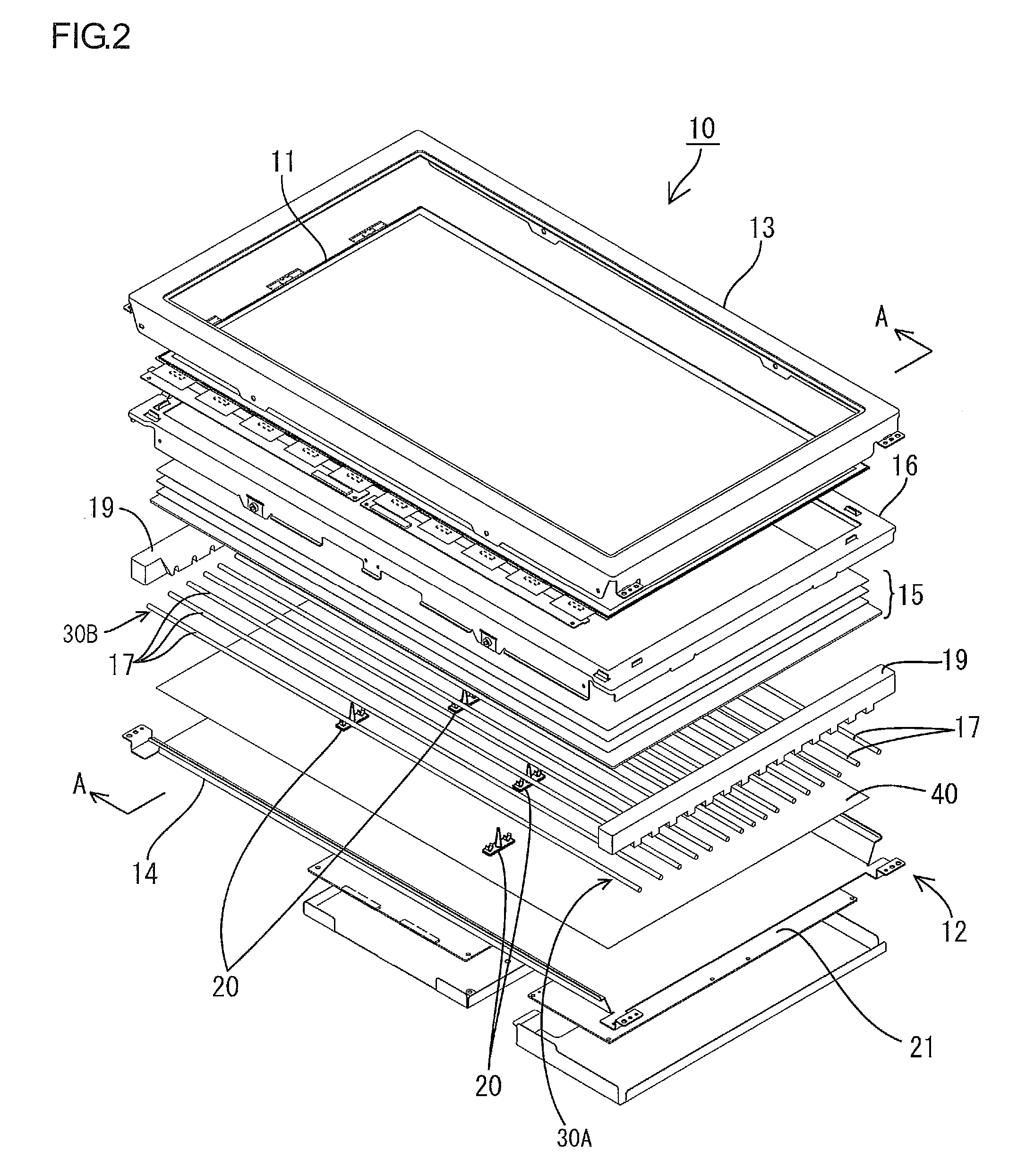
[0036]FIG. 1 is an exploded perspective view showing the general construction of a television receiver according to the present embodiment. FIG. 2 is an exploded perspective view showing the general construction of a liquid crystal display device. FIG. 3 is a sectional view showing the general construction of the liquid crystal display device along the line A-A. FIG. 4 is an explanatory diagram schematically showing the construction and operational effects of a characteristic part of a backlight device. FIG. 5 is a plan view schematically showing the construction of a light reflecting sheet.

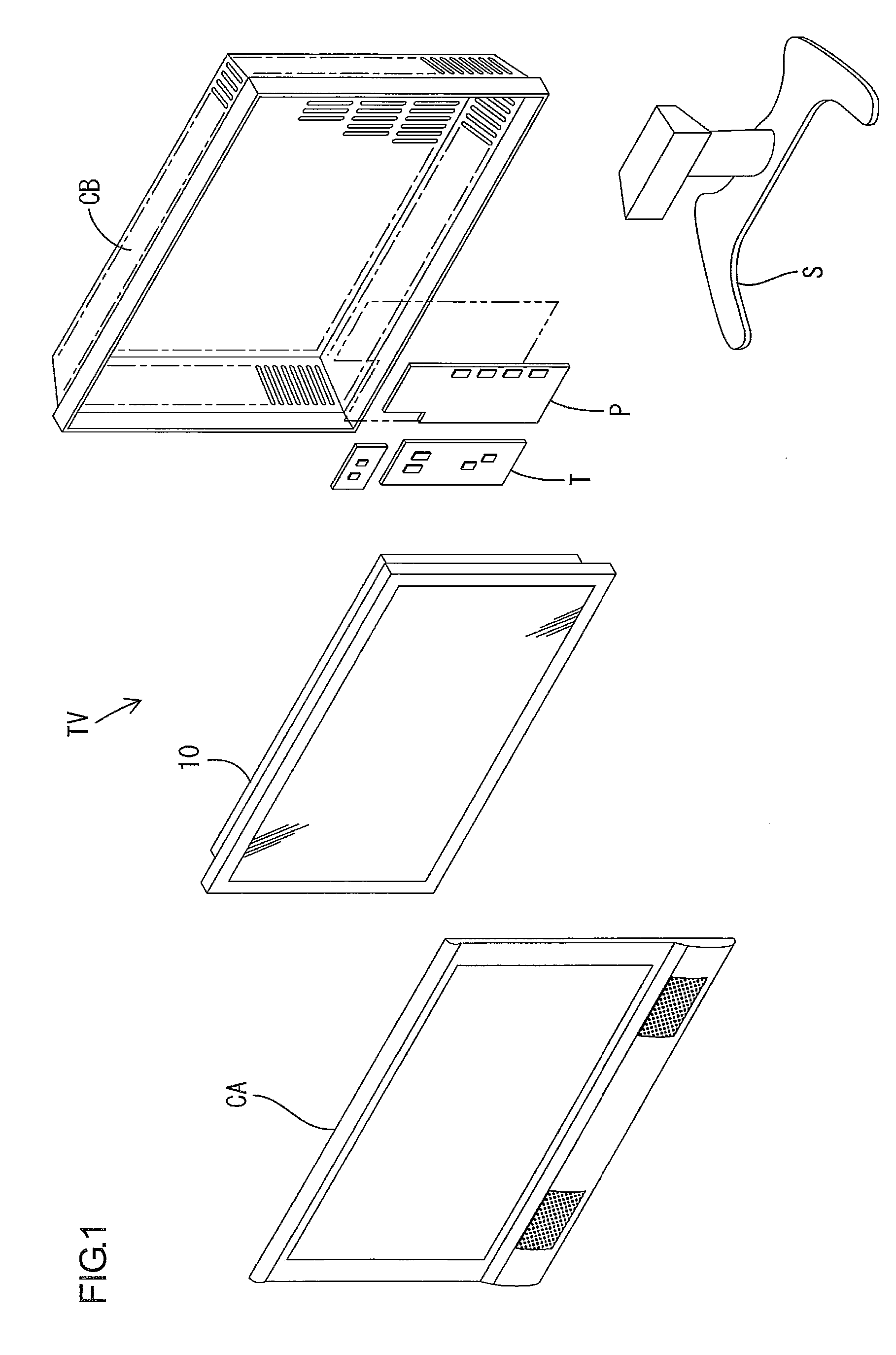
[0037]Referring to FIG. 1, the television receiver TV according to the present embodiment includes a liquid crystal display device 10, and front and back cabinets CA and CB capable of holding the liquid crystal display device 10 therebetween. Further included are a power source P, a tuner T a...

embodiment 2

[0067]Next, an embodiment 2 of the present invention will be explained with reference to FIG. 6.

[0068]In the above embodiment 1, the arrangement of the opening sections 50 is determined solely based on the difference in illumination brightness between the narrow-interval area 17A and the wide-interval areas 17B. In the present embodiment, the arrangement of opening sections 51 is determined further based on the difference in illumination brightness due to voltage difference among areas of cold cathode tubes 17. The other constructions are similar to the above embodiment 1. Therefore, the same parts as the above embodiment are designated by the same symbols, and redundant explanations are omitted. FIG. 6 is a plan view schematically showing the construction of a light reflecting sheet according to the present embodiment.

[0069]An inverter board 21 for supplying drive voltage to the cold cathode tubes 17 is mounted on one side of the backlight chassis 14 corresponding to a long-side-di...

embodiment 3

[0078]Next, an embodiment 3 of the present invention will be explained with reference to FIG. 7. The difference from the above embodiments 1 and 2 is in the arrangement of opening sections and the shapes of through holes. The other constructions are similar to the above embodiments. Therefore, the same parts as the above embodiments are designated by the same symbols, and redundant explanations are omitted. FIG. 7 is a plan view schematically showing the construction of a light reflecting sheet according to the present embodiment.

[0079]Referring to FIG. 7, through holes 23 and opening sections 52 are formed on the light reflecting sheet 42. Each through hole 23 has a square shape. On the other hand, the opening sections 52 have circular or oval shapes of varying planar dimension.

[0080]The opening sections 52 are arranged in a row along the long-side direction of the light reflecting sheet 42 (or along the axial direction of the cold cathode tube 17). In the areas of the light reflec...


PUM


Abstract

The present invention includes a plurality of linear sources 17 arranged parallel to one another, and a light reflecting member 40 arranged on the side of the linear light sources 17 that corresponds to the opposite side of the light emitting side. The linear light sources 17 are arranged so that a narrow-interval area 17A where the arrangement interval thereof is relatively narrow and a wide-interval area 17B where the arrangement interval is relatively wide are provided. The light reflecting member 40 includes an opening section 50 located directly below the linear light sources 17. The opening section 50 is provided so that the opening ratio as a ratio between a total area of the light reflecting member 40 and areas of the opening section 50 is higher at an area of the light reflecting member 40 corresponding to the narrow-interval area 17A than at an area of the light reflecting member 40 corresponding to the wide-interval area 17B.

Description

TECHNICAL FIELD[0001]The present invention relates to a lighting device, a display device and a television receiver.BACKGROUND ART[0002]In a display device having non-luminous optical elements as typified by a liquid crystal display device, a backlight device is provided on the backside of a display panel such as a liquid crystal panel, so as to illuminate the display panel (as shown in Patent Document 1, for example).[0003]In order to prevent reduction in luminescent efficiency of light sources attributable to their own heat, Patent Document 1 discloses a technique that provides at least one opening section on a reflective member arranged across a plurality of light sources from a liquid crystal display element, so that the opening section is located to correspond to the orthogonal projection of a light source onto the reflective member, which can be obtained by projecting the light source along a direction perpendicular to the display surface of the liquid crystal display element....

Claims


Application Information

Patent Timeline
IPC IPC(8): H04N5/44F21V1/00G02F1/13357F21S2/00F21V7/00F21V7/10F21V7/22F21Y103/00H04N5/66
CPCG02F1/133604G02F1/133605G02F1/133611G02F2001/133613G02F1/133613
Inventor KUROMIZU, YASUMORIYOKOTA, MASASHISHIMIZU, MASAKI
Owner SHARP KK
Why Eureka
Try Eureka