
Ophthalmic endoillumination using fiber generated light

Active Publication Date: 2010-07-22
ALCON INC
View PDF3 Cites 24 Cited by
  • Summary
  • Abstract
  • Description
  • Claims
  • Application Information

AI Technical Summary

Problems solved by technology

Syneresis results in shrinkage of the vitreous body, which can exert pressure or traction on its normal attachment sites.
If enough traction is applied, the vitreous body may pull itself from its retinal attachment and create a retinal tear or hole.

Method used


Image

  • Ophthalmic endoillumination using fiber generated light
  • Ophthalmic endoillumination using fiber generated light
  • Ophthalmic endoillumination using fiber generated light

Examples


Embodiment Construction

[0020]Preferred embodiments of the present invention are illustrated in the Figures, like numerals being used to refer to like and corresponding parts of the various drawings.

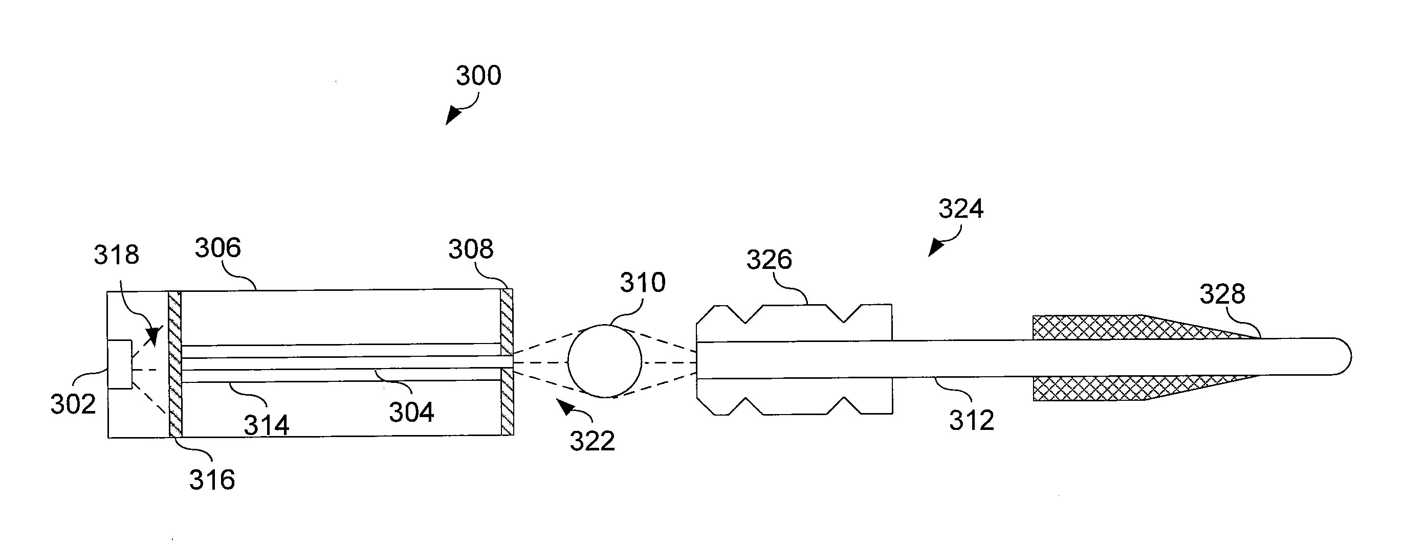
[0021]Embodiments of the present invention provide an ophthalmic endoilluminator is that includes one or more pump light sources, an optical fiber, such as the scintillator fiber or fluorescent fiber. The optical fiber couples to the pump light sources to receive an output of the pump light sources and produce an optical output, such as white light in certain embodiments of the scintillator fiber having a white phosphor in either the core or cladding or red-green-blue (RGB) outputs in the case of certain embodiments using dyed fluorescent fibers. An optical coupling element coupled to the optical fiber receives the optical output and provides the optical output to an endoilluminator fiber which conducts the light into an interior region of the eye.

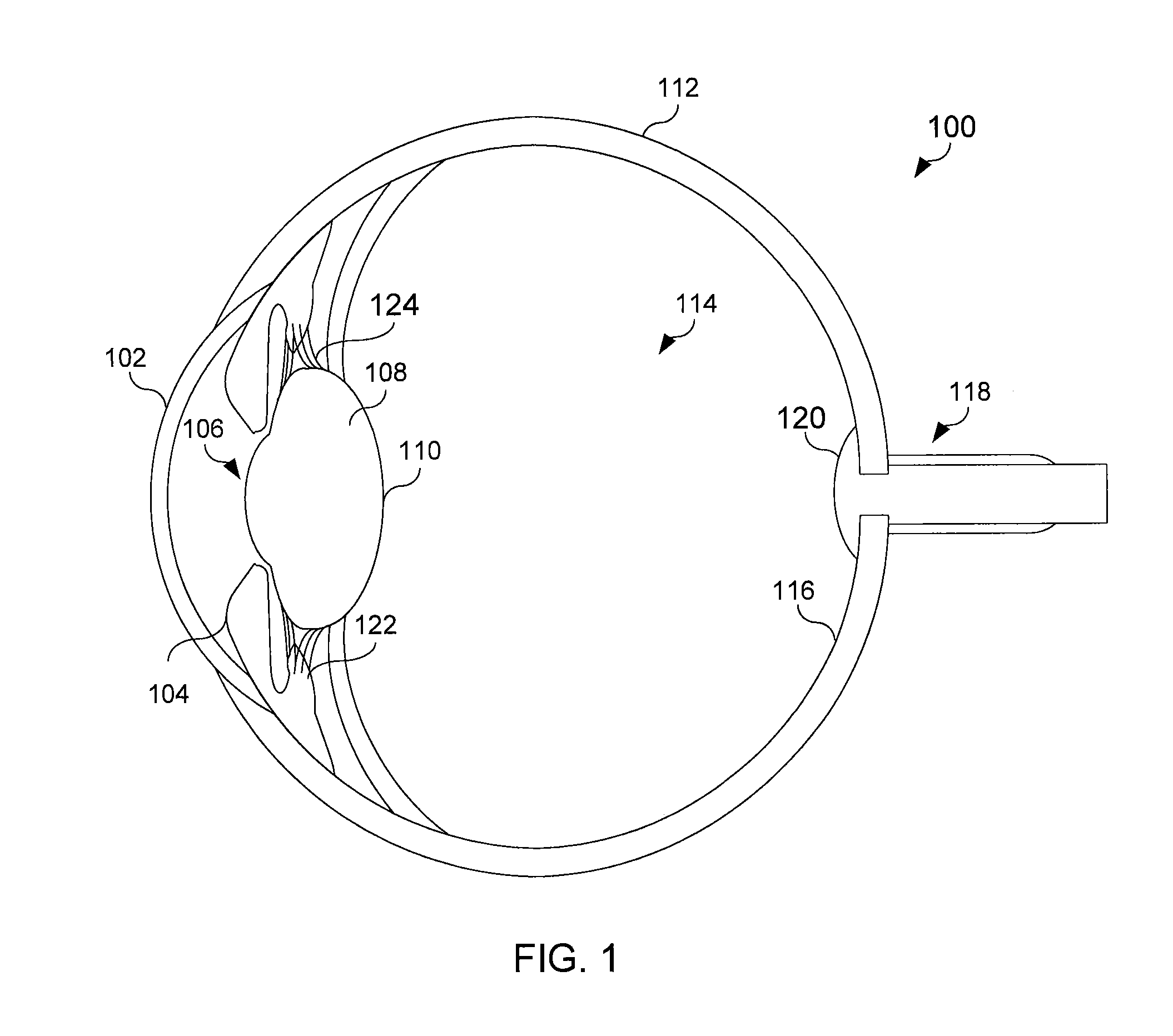
[0022]FIG. 1 illustrates the anatomy of the eye into which the i...


PUM


Abstract

In one aspect of the invention, an ophthalmic endoilluminator includes at least one pump light source and a scintillator fiber optically coupled to the pump light source. The scintillator fiber receives an output of the pump light source and produces light in a different wavelength range than the output of the pump light source. An optical coupling element couples the light to an optical fiber, which conducts the light into an eye.

Description

RELATED APPLICATIONS[0001]This application claims priority to U.S. provisional application Ser. No. 61 / 146,173 filed on Jan. 21, 2009, the contents which are incorporated herein by reference.TECHNICAL FIELD OF THE INVENTION[0002]The present invention relates to an illuminator for use in ophthalmic surgery and more particularly to an ophthalmic endoilluminator to produce a light suitable for illuminating the inside of an eye.BACKGROUND OF THE INVENTION[0003]Anatomically, the eye is divided into two distinct parts—the anterior segment and the posterior segment. The anterior segment includes the lens and extends from the outermost layer of the cornea (the corneal endothelium) to the posterior of the lens capsule. The posterior segment includes the portion of the eye behind the lens capsule. The posterior segment extends from the anterior hyaloid face to the retina, with which the posterior hyaloid face of the vitreous body is in direct contact. The posterior segment is much larger than...

Claims


Application Information

Patent Timeline
IPC IPC(8): A61B3/10
CPCA61B1/0661A61B90/30A61B2090/306A61B3/0008A61B90/36A61B1/0684A61B1/07A61F9/00A61F9/007
Inventor ARTSYUKHOVICH, ALEXANDER N.BUCZEK, MARKDACQUAY, BRUNOYADLOWSKY, MICHAEL J.
Owner ALCON INC
Learn More