
Wireless communication system, mobile station , and base station

Inactive Publication Date: 2010-07-22
HITACHI LTD
View PDF11 Cites 44 Cited by
  • Summary
  • Abstract
  • Description
  • Claims
  • Application Information

AI Technical Summary

Benefits of technology

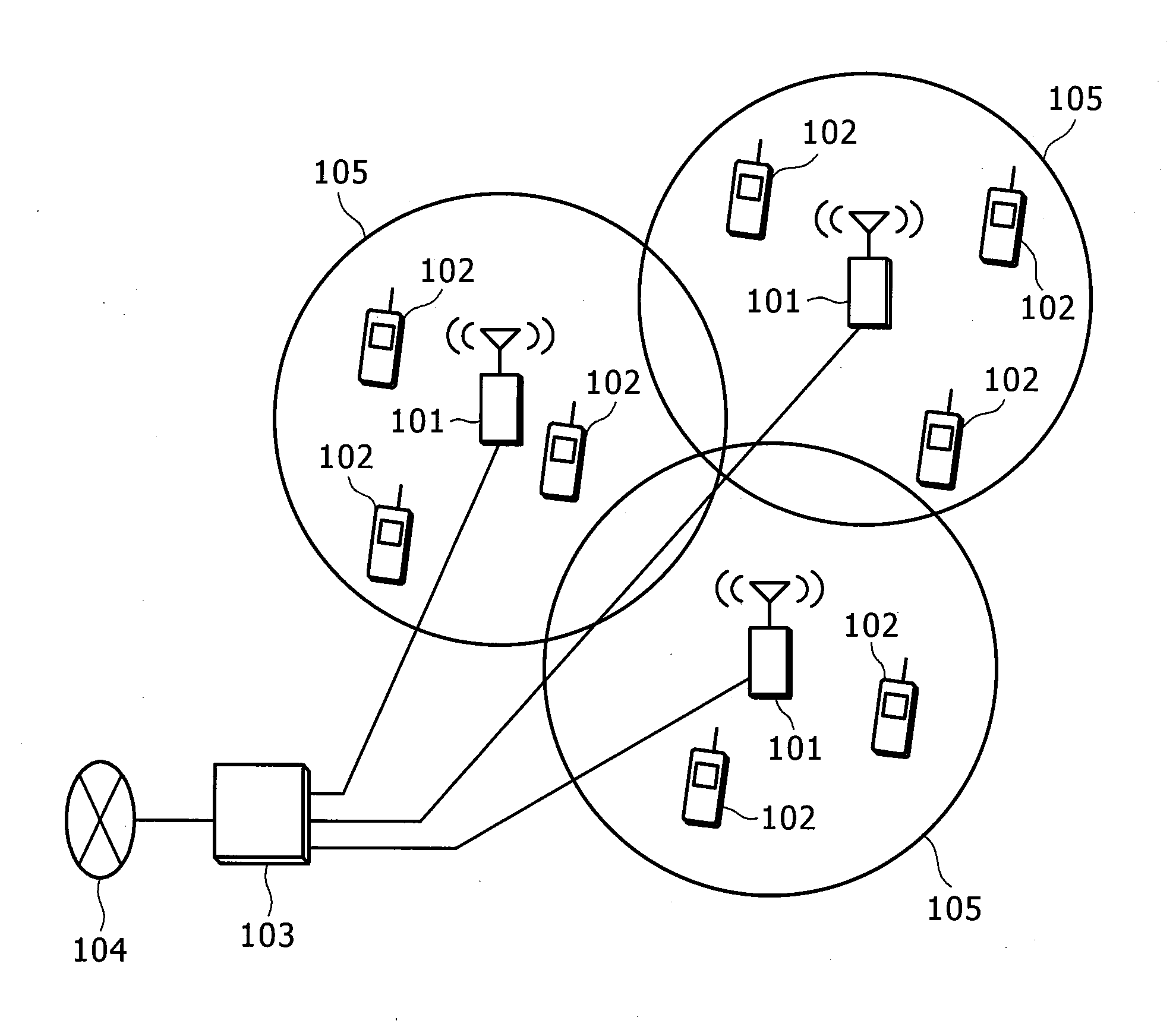
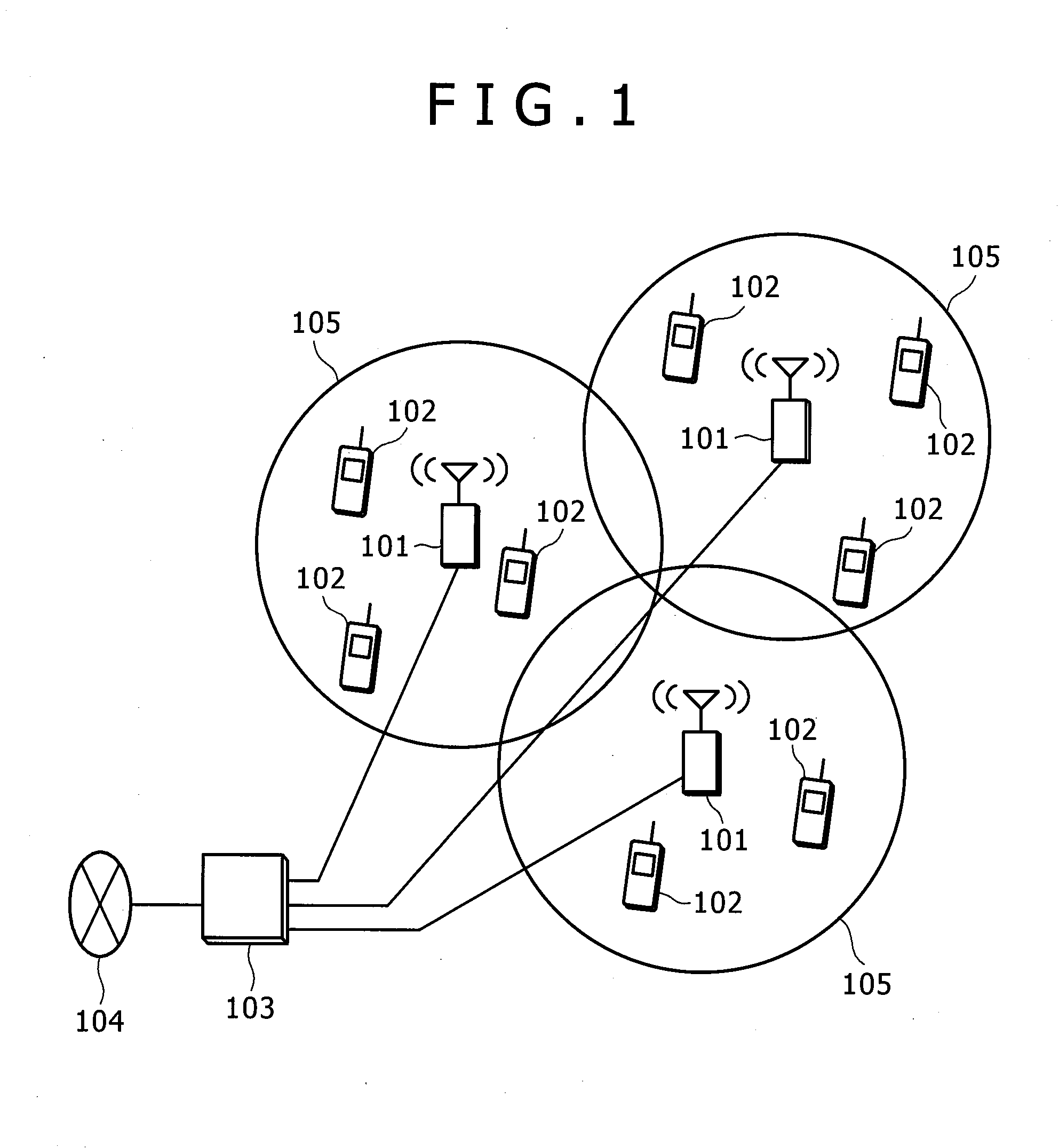
[0010]Information on downlink transmit power is transmitted through X2 per minimum unit of subcarrier assignment called RB (Resource Block). This information is called RNTP (Relative Narrowband Transmit Power Indication). Each BS is able to know the subcarrier on which a neighbor BS transmits with a larger transmit power, using the RNTP signaled from the neighbor BS. On a subcarrier on which a neighbor BS transmits with larger transmit power, MSs communicating with the BS will receive larger interference power. Because an MS located at a cell edge is nearer to a neighbor BS, such MS tends to receive larger interference power than an MS located in the cell center. Therefore, the BS assigns a subcarrier on which a neighbor BS transmits with smaller transmit power, to a cell-edge MS which is more susceptible to interference and assigns a subcarrier on which the neighbor BS transmits with larger transmit power, to a cell-center MS which is less susceptible to interference. Thereby, it is possible to suppress interference power that each MS receives under a given level.
[0011]Uplink subcarrier assignment information is also transmitted through X2 as HII (High Interference Indication). HII includes information on RBs assigned to cell-edge MSs. Generally, MSs located at the cell edge of a BS and MSs located at the cell edge of a neighbor BS are likely to be sources of interference with each other. Thus, making use of information signaled by HII, a BS determines a subcarrier to be assigned to a cell-edge MS by selecting it among subcarriers other than those assigned by a neighbor BS to cell-edge MSs in the neighbor cell, so that mutual interference between cell-edge MSs in both cells can be suppressed.
[0015]In downlink, frequencies on which a BS transmits with a large transmit power, e.g., subcarriers assigned to cell-edge MSs produce a large interference to an MS communicating with a neighbor BS. The assignment of distributed frequency resources to a cell-edge MS can avoid a condition that the transmit power is high in a particular frequency band and disperses the interference affecting MSs served by the neighbor BS. It is thus possible to suppress interference experienced by MSs served by the neighbor BS.
[0016]For uplink transmission, distributed frequency resources are assigned to a cell-edge MS. Subcarriers assigned to cell-edge MSs produce a large interference to a neighbor BS. However, the assignment of distributed frequency resources to a cell-edge MS can avoid a situation that the interference power received by the neighbor BS is high in a particular frequency band and disperses the interference. Also, even in a case where a high interference power is received from an MS communicating with a neighbor BS in a particular frequency band, by the assignment of distributed frequency resources to a cell-edge MS, a frequency diversity benefit is obtained, because the interference power varies with frequencies or subcarriers.
[0018]According to an aspect of the present invention, each BS can perform autonomous subcarrier assignments without using information on frequency usage at a neighbor BS. Thereby, resource assignments can be performed adaptively, according to traffic to be handled by each BS and how many MSs connect to the BS, without depending on information signaled in a long period, such as parameters transmitted via the X2 interface.

Problems solved by technology

Generally, MSs located at the cell edge of a BS and MSs located at the cell edge of a neighbor BS are likely to be sources of interference with each other.
However, it takes about 20 milliseconds to transmit information via the X2 interface.

Method used


Image

  • Wireless communication system, mobile station , and base station
  • Wireless communication system, mobile station , and base station
  • Wireless communication system, mobile station , and base station

Examples


first embodiment

[0069]The following describes a first embodiment to which the present invention is applied. In the first embodiment, resource assignment of Type 1 is carried out for cell-edge MSs in order to disperse interference by adjusting the interference power from a neighbor BS experienced by the cell-edge MSs in downlinks by appropriate RB assignments, and moreover, to disperse interference affecting MSs communicating with the neighbor BS in the frequency domain.

[0070]FIG. 9 illustrates an example of classifying MSs into the areas. In FIG. 9, as for MSs communicating with a BS eNB1, an MS UE1 is classified into the cell-center area (area 1) and an MS UE2 is classified into the cell-edge area (area 2). As for MSs communicating with a BS eNB2, an MS UE3 is classified into the cell-center area (area 1) and an MS UE4 is classified into the cell-edge area (area 2). The following description assumes that MSs are classified into the areas as in FIG. 9.

[0071]FIG. 10 illustrates an RB assignment proc...

second embodiment

[0074]The following describes a second embodiment to which the present invention is applied. In the second embodiment, resource assignment of Type 1 is carried out for MSs for which transmit power per RB is more than a given value in order to disperse interference caused by RBs with a large transmit power in downlinks.

[0075]FIG. 12 illustrates an RB assignment procedure which is performed at BS in the present embodiment. First, BS divides frequency resources available in the system into resources (Type 1 resources) to be assigned to MSs for which transmit power per RB is large and resources (Type 0 resources) to be assigned to MSs for which transmit power per RB is small. The division of the resources is carried out by reserving one of more RBG subsets as the Type 1 resources (1201). Then, BS performs resource assignment of Type 0 or Type 1, according to the transmit power per RB of each MS 1202. If the transmit power per RB for MS is equal to or more than a preconfigured threshold ...

third embodiment

[0077]The following describes a third embodiment to which the present invention is applied. In the third embodiment, resource assignment of Type 1 that makes it easy to stabilize communication equality is carried out for cell-edge MSs in order to stabilize the communication equality of cell-edge MSs in downlinks.

[0078]The following description assumes that MSs are classified into the areas as in FIG. 9.

[0079]FIG. 14 illustrates an RB assignment procedure which is performed at BS in the present embodiment. First, BS classifies MSs communicating with the BS that executes RB assignment into the plural areas (1401). In the example of FIG. 14, if RSRP signaled from an MS is equal to or more than a predetermined threshold value, BS judges that the distance from the BS to the MS is rather short and classifies the MS into the cell-center area; if the RSRP is less than the threshold value, BS judges that the distance from the BS to the MS is rather long and classifies the MS into the cell-ed...


PUM


Abstract

In a conventional OFDMA / SCFDMA communication scheme, frequency resource assignment information is exchanged between BSs via a wired interface and used for control of inter-cell interference or the like. When a BS performs assignments of frequency resources, taking the status of a neighbor BS signaled via the wired interface into account, it might be impossible to follow a change in the status of the assignments of frequency resources at the neighbor BS due to a delay occurring in the wired interface. BS selects and assigns distributed frequency resources or continuous frequency resources, depending on the position of an MS in the cell and the transmit power of the BS.

Description

CLAIM OF PRIORITY[0001]The present application claims priority from Japanese patent application JP 2009-10495 filed on Jan. 21, 2009, the content of which is hereby incorporated by reference into this application.BACKGROUND OF THE INVENTION[0002]The present invention relates to a wireless communication system, mobile station (MS), and base station (BS) pertaining to a communication system adopting OFDMA (Orthogonal Frequency Division Multiple Access) and realizing cellular communication.[0003]As a method for multiplexing users in wireless communication, OFDMA is often adopted. In OFDMA, simultaneous access by plural mobile stations (MSs) is realized by assigning a subset of many subcarriers predefined by the OFDM scheme to each MS. In the OFDMA scheme, it is necessary to perform assignment of subcarriers to be used for data communication before data transmission is performed. For example, in a cellular wireless system adopting the OFDMA scheme, a base station (BS) determines subcarr...

Claims


Application Information

Patent Timeline
IPC IPC(8): H04W72/04H04J1/00H04J11/00H04L27/01H04W72/08H04W72/10
CPCH04W16/30H04W72/042H04W72/048H04W72/085H04W72/51H04W72/23H04W72/542
Inventor KATAYAMA, RINTAROTAKEUCHI, KEISUKEYAMAMOTO, TOMONORIUWANO, KOKI
Owner HITACHI LTD
Learn More