Geodetic Apparatus

Inactive Publication Date: 2010-07-29
TRIMBLE JENA
View PDF8 Cites 0 Cited by
  • Summary
  • Abstract
  • Description
  • Claims
  • Application Information

AI Technical Summary

Benefits of technology

[0010]According to another advantageous example the worm thread of the worm extends in a single plane. In this way, inner friction forces of the first gear unit can be kept low while the worm thread has a simple construction.
[0011]According to another advantageous example the worm thread spirally extends by at least 360°. This allows a wide range of fine adjustments even if a high gearing ratio is selected.
[0012]The worm and the worm gear can be manufactured in any different ways. According to an advantageous example, however, the worm is at least partially made of a plastic material, preferably by injection molding. In this way, the manufacture of the geodetic apparatus can be further simplified since the worm can be produced without expensive and time consuming machining of metal parts or the like. This was not possible with known, non-planar worms since injection molding of non-planar worms induced burs and ridges on the worm which impaired the operation of the gear unit.
[0013]Another advantage of using a planar worm is that such a planar worm can, according to another advantageous example, be provided with at least one further gearing w

Problems solved by technology

While this device generally works properly, it requires parts which are relatively complicated to manufacture such as the worm.
Thus, the known adjustment devic

Method used


Image

  • Geodetic Apparatus
  • Geodetic Apparatus
  • Geodetic Apparatus

Examples


first embodiment

[0025]the first gear unit 10 is schematically shown in a partial view in FIG. 3. In this embodiment, the first gear unit 10 comprises a worm 20 and a worm gear 30 meshing with each other. The worm 20 has a plate like body 22. On a first side face 22′ of the plate like body 22 a spirally extending worm thread 24 is formed in such a way that it extends in a single plane by about 720° along the outer periphery of the first side face 22′. In the present embodiment, the worm 20 is made of a plastic material by injection molding or another suitable process. Of course, the shape and material of the worm 20 is not limited on the described features but can varied in various ways.

[0026]As shown in FIG. 3, the first gear unit 10 further comprises a worm gear 30 which, in the present embodiment, is formed by a pinion gear. Further, it is to be noted that the teeth of the worm gear 30 may also be arranged along a circle on a side face of the worm gear 30 or even in inclined manner. In the presen...

second embodiment

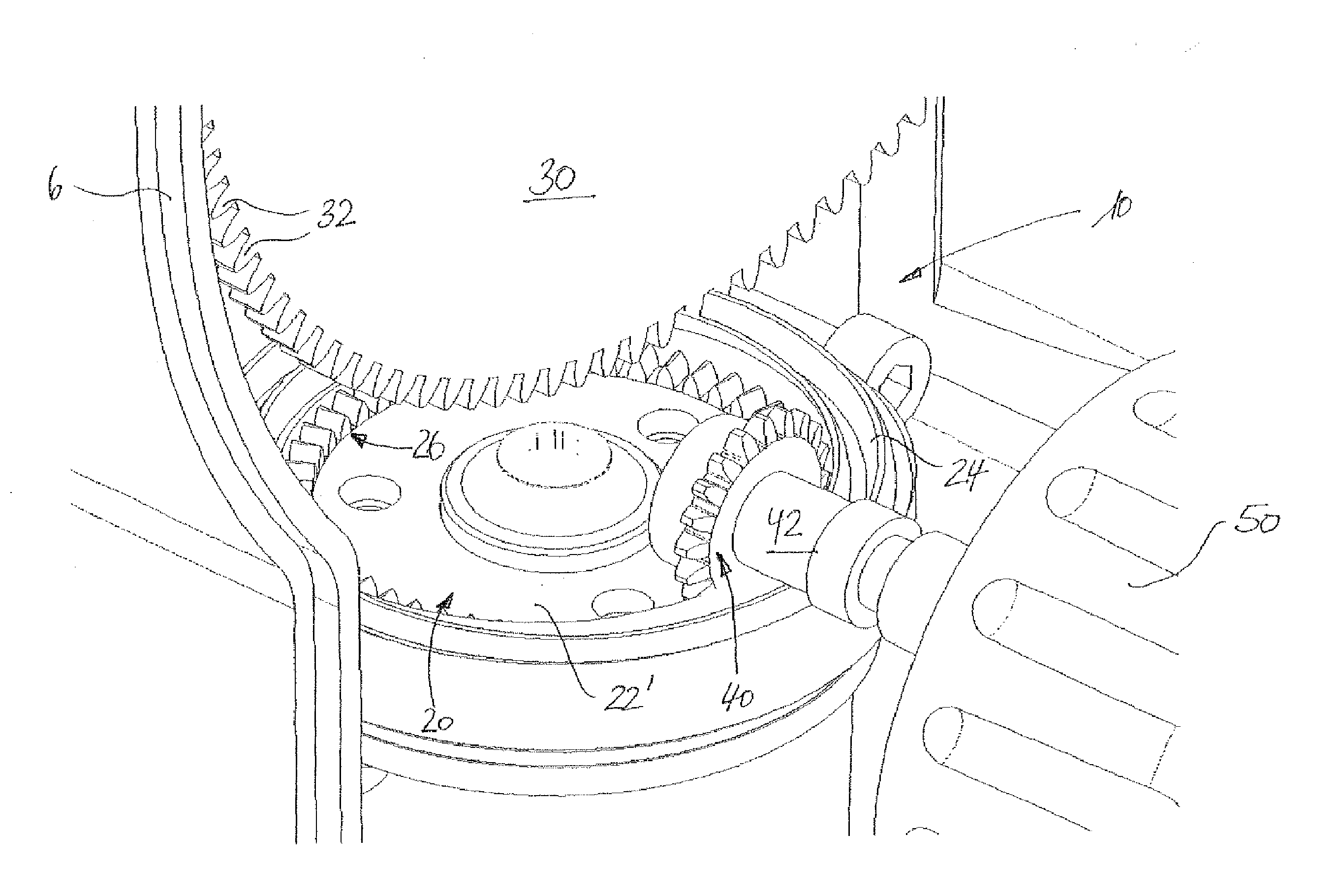
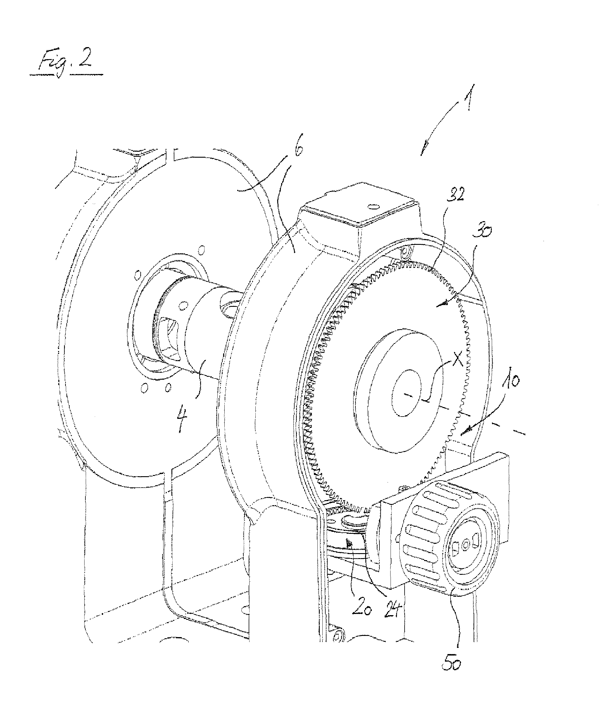
[0028]FIGS. 4 and 5 schematically show the first gear unit 10 in the geodetic apparatus 1 according to the present invention. In FIGS. 4 and 5, same or corresponding components are designated with the same reference numerals, and a repeated discussion thereof is omitted.

[0029]As shown in FIGS. 4 and 5, the worm of the second embodiment comprises a further gearing 26 in the form of rack teeth which are arranged along a circle on the first side face 22′ of the worm 20.

[0030]A drive gear 40, a pinion in this embodiment, meshes with the further gearing 26 of the worm and is fixed on a shaft 42 which is connected to the thumb wheel 50 or other suitable drive means. In this way, the reduction gear ratio of the first gear unit 10 can be further increased by maintaining a simple construction and easy manufacture.


PUM


Abstract

A geodetic apparatus, in particular tacheometer or theodolite, comprises an optical device for sighting objects, a first support on which the optical device is supported such that the optical device may turn around a first axis, and a first gear unit for transmitting a drive torque on the optical device so as to turn the optical device around the first axis. In thegeodetic apparatus, the first gear unit comprises a worm and a worm gear meshing with each other, wherein the worm has a plate-like body and a spirally extending worm thread is formed on a first side face of the body, and the worm gear has a plurality of teeth evenly distributed along a circle.

Description

CROSS-REFERENCES TO RELATED APPLICATIONS[0001]The present application claims priority to International Patent Application No. PCT / EP2007 / 057659, filed on Jul. 25, 2007, entitled “Geodetic Apparatus,” the contents of which is hereby incorporated by reference in its entirety.BACKGROUND OF THE INVENTION[0002]The present invention generally relates to a geodetic apparatus, in particular a tacheometer or a theodolite.[0003]A geodetic apparatus such as a tacheometer or theodolite is generally used for sighting or focusing objects and for determining their (relative) position. For this purpose, a geodetic apparatus generally comprises an optical device for sighting or focusing said objects, for instance a lens, telescope, camera or the like.[0004]In the geodetic apparatus, the optical device is supported such that it may turn around a first axis so as to aim at an object. For turning and adjusting the optical device, various adjustment means are known in the art. For instance, U.S. Pat. No...

Claims


Application Information

Patent Timeline
IPC IPC(8): G01C1/02G12B5/00
CPCG01C1/02G01C15/00Y10T74/19828
Inventor PETERMANN, MARCO
Owner TRIMBLE JENA
Why Eureka
Try Eureka