
Ski slope snow tiller

a technology of snow tiller and ski slope, which is applied in the direction of ski bindings, sports equipment, ways, etc., can solve the problems of increased weight of the tiller, inability to prevent accumulation, and inability to produce, so as to achieve the effect of easy production

Active Publication Date: 2010-07-29
PRINOTH SPA
View PDF5 Cites 4 Cited by
  • Summary
  • Abstract
  • Description
  • Claims
  • Application Information

AI Technical Summary

Benefits of technology

[0005]It is an object of the present invention to provide a tiller designed to eliminate as far as possible the drawbacks of the known art, while at the same time being cheap and easy to produce.
[0006]According to the present invention, there is provided a ski slope snow tiller, the tiller comprising a frame connected to a tractor movable in a travelling direction; a shaft fitted with tools for working the snow cover; a casing surrounding the shaft; and a mat towed over the surface of the snow cover, behind the casing; the tiller being characterized by comprising a guard located at least over the casing and the mat, to prevent snow accumulating.

Problems solved by technology

Though highly effective in tilling snow on ski slopes, tillers of this sort have a tendency to accumulate, or at least fail to prevent accumulating, snow, which, be it produced by snowfall or thrown up by the tiller or the tractor to which the tiller is connected, deposits in particular on the part of the tiller between the casing the mat.
This added weight on the tiller has numerous drawbacks increased power consumption of the tractor; impaired maneuverability of the tractor and tiller as a whole; potential damage to the component parts of the tiller; increased wear of the tiller; and the necessity to clean the snow off the tiller before garaging the tractor and tiller, to prevent flooding the garage when the snow melts.

Method used


Image

  • Ski slope snow tiller
  • Ski slope snow tiller
  • Ski slope snow tiller

Examples


Embodiment Construction

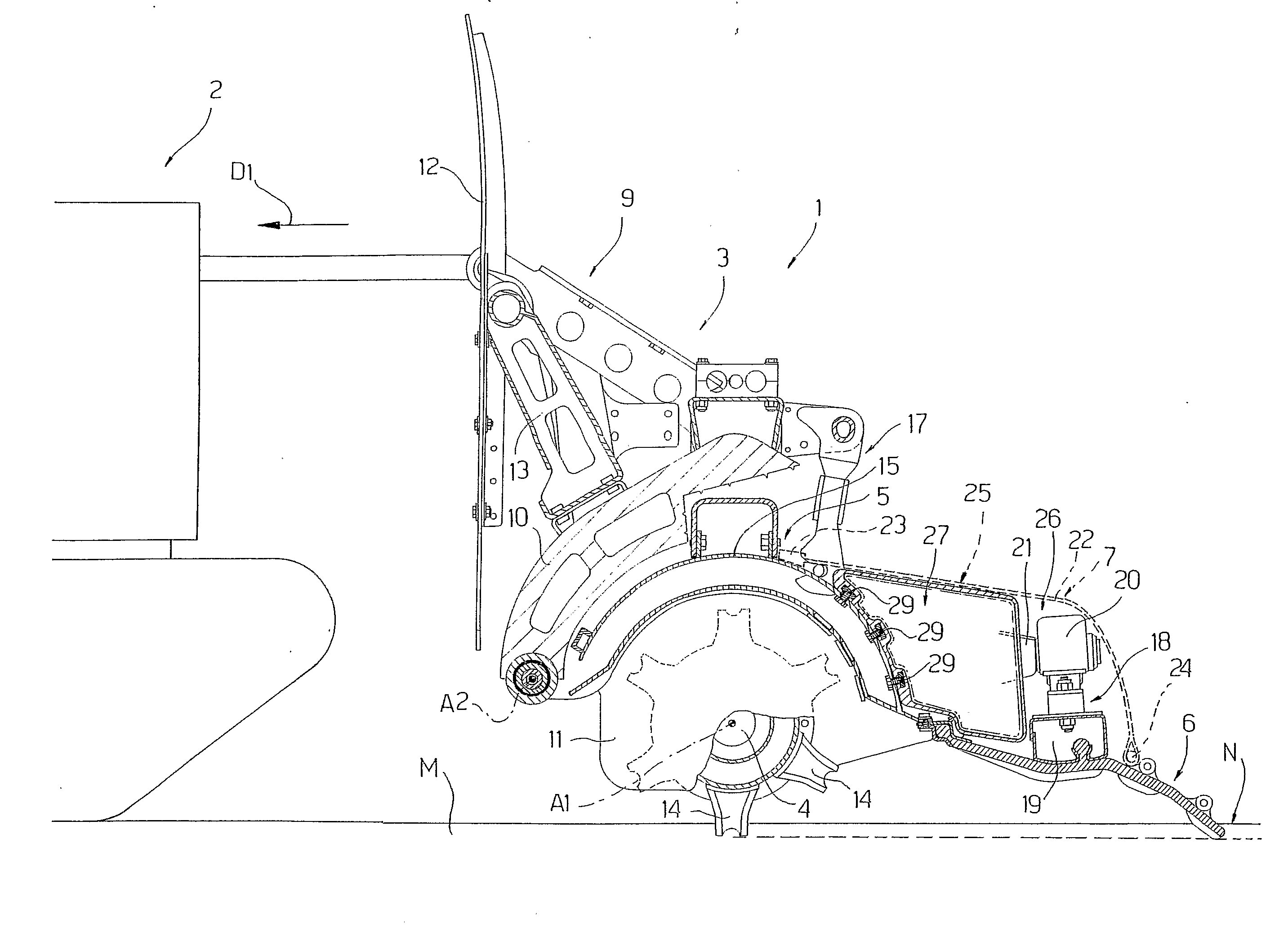
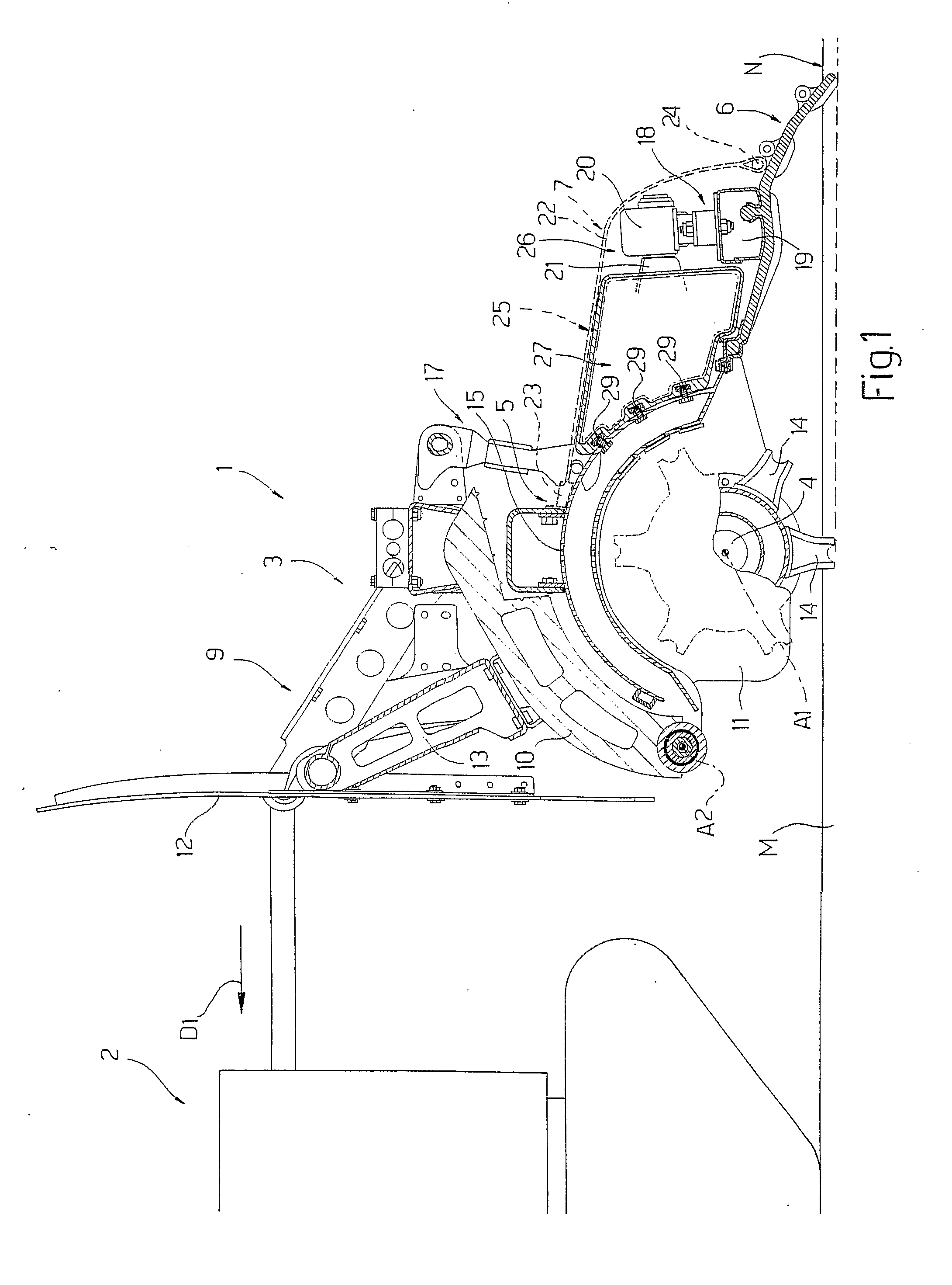
[0014]Number 1 in FIG. 1 indicates as a whole a tiller for tilling the snow cover M of ski slopes, and which is connectable to a tractor 2 defined, in the example shown, by a crawler vehicle for travelling over snow-covered slopes and for supporting and towing tiller 1 in a travelling direction D1.

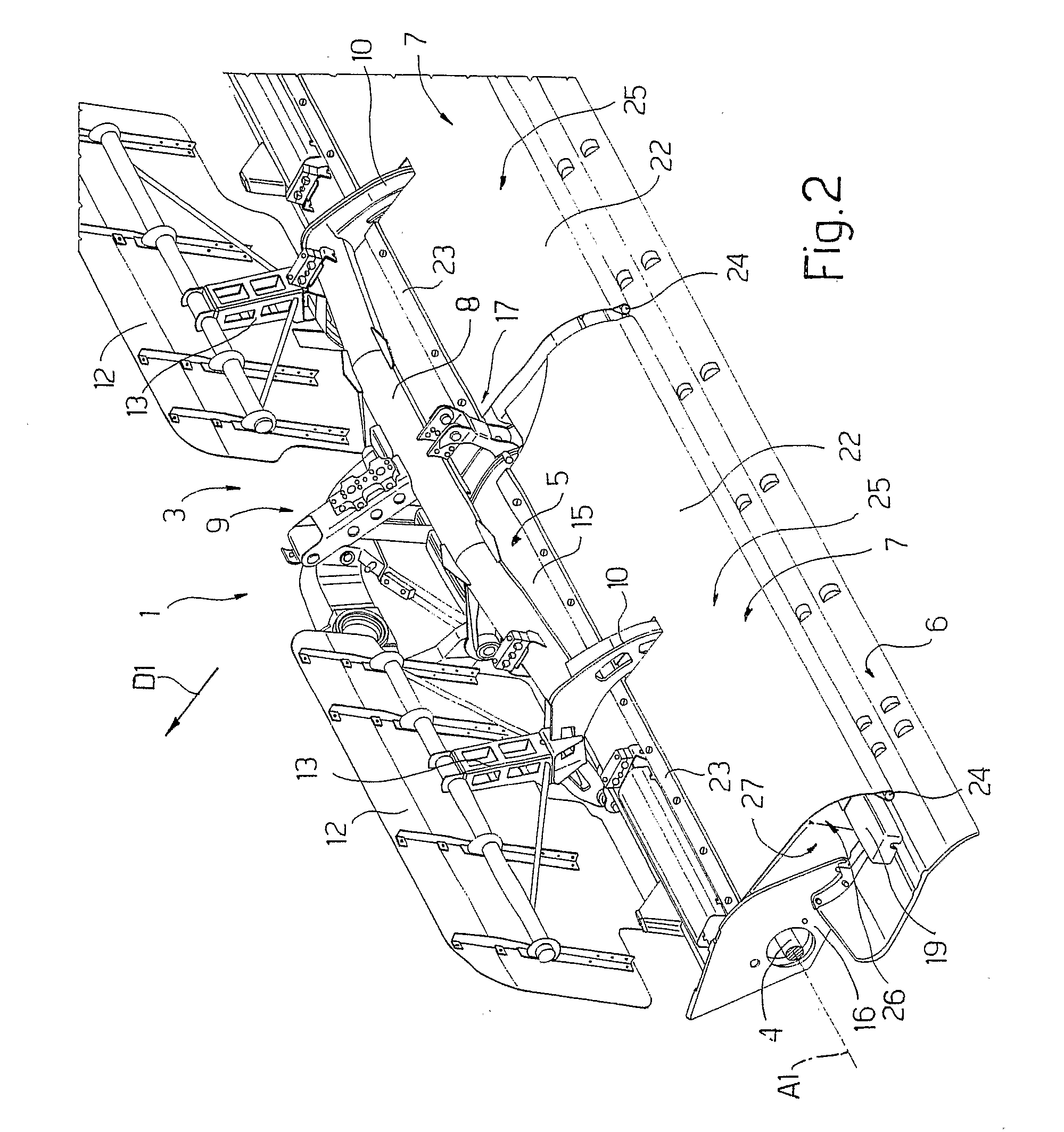
[0015]Tiller 1 is designed to work a surface portion of snow cover M, and comprises a frame 3; a shaft 4 mounted to rotate with respect to frame 3 about an axis A1, and extending crosswise to travelling direction D1; a protective casing 5 enclosing shaft 4; a normally flexible mat 6 connected to casing 5 and towed over the surface N of snow cover M; and a guard 7 fitted over casing 5 and mat 6 to prevent slow accumulating between casing 5 and mat 6.

[0016]With reference to FIG. 2, frame 3 comprises a bar 8 substantially parallel to axis A1; a hitch device 9 fixed to bar 8 and for connecting tiller 1 to tractor 2; two arc-shaped segments 10 fixed to and crosswise to bar 8; and plates 11 (FIG...


PUM


Abstract

A ski slope snow tiller having a frame connected to a tractor movable in a travelling direction; a shaft crosswise to the travelling direction and fitted with tools for working the snow cover; a casing surrounding the shaft; a mat towed over the surface of the snow cover, behind the casing; and a guard located at least over the casing and the mat, to prevent snow accumulating.

Description

TECHNICAL FIELD[0001]The present invention relates to a ski slope snow tiller.BACKGROUND ART[0002]A ski slope snow tiller normally comprises a frame connected to a tractor movable in a travelling direction; a shaft fitted with snow-working tools; a casing surrounding the shaft; and a mat towed over the snow surface, behind the casing.[0003]Though highly effective in tilling snow on ski slopes, tillers of this sort have a tendency to accumulate, or at least fail to prevent accumulating, snow, which, be it produced by snowfall or thrown up by the tiller or the tractor to which the tiller is connected, deposits in particular on the part of the tiller between the casing the mat.[0004]The amount of snow accumulated on the tiller depends on the width of the tiller, and, according to the Applicant's findings, may be as much as 600 kg. This added weight on the tiller has numerous drawbacks increased power consumption of the tractor; impaired maneuverability of the tractor and tiller as a wh...

Claims


Application Information

Patent Timeline
Patent Type & Authority Applications(United States)
IPC IPC(8): E01H4/02E01H4/00
CPCE01H4/02
Inventor DALLA TORRE, ANDREASRUNGGALDIER, MARTIN
Owner PRINOTH SPA
Learn More