Ballistic construction panel

a technology of construction panels and ballistics, applied in construction, building components, construction materials, etc., can solve the problems of increased danger to personnel stationed in the middle east, increased risk of shooting and/or fragmentation of shrapnel, and inability to resist high-velocity projectiles, etc., to achieve the effect of convenient transportation and light weigh

Inactive Publication Date: 2010-07-29
HUGHES JR JOHN P
View PDF43 Cites 16 Cited by
  • Summary
  • Abstract
  • Description
  • Claims
  • Application Information

AI Technical Summary

Benefits of technology

[0011]It is a first advantage of the present invention to provide a construction panel which is resistant to substantially any conventional small-arms munitions.
[0012]It is a second advantage of the present invention to provide a ballistic resistant construction panel which is light-weight and readily transportable.
[0013]It is a third advantage of the present invention to provide a ballistic resistant construction panel that may be modified to address the potential threat level by adding additional layers of protection.
[0014]It is a fourth advantage of the present invention to provide a ballistic resistant construction panel that contains a earthen filler material, such as sand, that does not have to be shipped to a location as part of its ballistic protection.
[0015]It is a fifth advantage of the present invention to form a construction panel by coupling relatively thin and rigid sheets of fiber-reinforced plastic material together. These sheets include a generally waveform shaped corrugated member that is sandwiched between two planar sheets. The corrugated member's shape creates a plurality of elongated channels along the panel and these channels are reinforced against ballistic attack by filling them with a solid filler material, such as sand.
[0016]It is a sixth advantage of the invention to provide a ballistic construction panel including a plurality of generally planar and rigid structural sheets. The sheets include an inner-most sheet and an outer-most sheet and wherein each of the sheets is disposed parallel to each other. At least one rigid corrugated member is disposed between each adjacent sheet and is coupled to these adjacent sheets. The corrugated member and adjacent sheets cooperate to define a plurality of elongated cells. A reinforcing filler material is disposed within and fills the plurality of cells.

Problems solved by technology

For example, during a military deployment or an emergency situation where an area's housing may be destroyed or made uninhabitable.
Additionally, conventional temporary shelters deployed in combat zones or other areas where violence may break out are often not resistant to high-velocity projectiles, gunfire and / or fragmentation shrapnel.
Currently, the Middle East is one such dangerous area.
The desert environment of the area poses additional dangers to personnel stationed there as the extreme temperatures must also be taken into account when erecting shelters.
Currently, temporary shelters are limited to traditional tents, which only offer limited protection against weather and to some pre-fabricated housing units which are no better than sheet-metal structures or cargo containers.
These shelters offer little to no ballistic protection to their occupants.
Additionally, with current shelters, deployment in certain environments, such as a desert, also highlights the fact that these shelters do not offer adequate thermal insulation.
Even if these shelters are ballistic resistant they usually achieve this resistance by using relatively expensive and exotic materials such as aramid fiber-based ballistic materials (e.g., Kevlar® or Nomex®) that are layered together to form panels.
This protection also suffers from the drawback that every component of the panel must be manufactured at first location, stored at another, and then brought to the site, thereby increasing the logistical difficulties and expenses.
Applying armor plating to existing conventional structures suffers from the drawback of lack of portability and high cost.
While age-old earthen defenses offer a cheap means for increasing survivability and are readily available at the deployment location, the very high manual labor requirements of building earthworks around temporary structures is not desirable.
Therefore, fortifying conventional structures using earthworks (e.g., sandbags) is not practical on a large scale.
Furthermore, the threat of terrorist activity, such as suicide-bombers, where an attack may occur from the inside of a structure may negate any armor or ballistic protection provided by the outer walls of a structure.

Method used


Image

  • Ballistic construction panel
  • Ballistic construction panel
  • Ballistic construction panel

Examples


Embodiment Construction

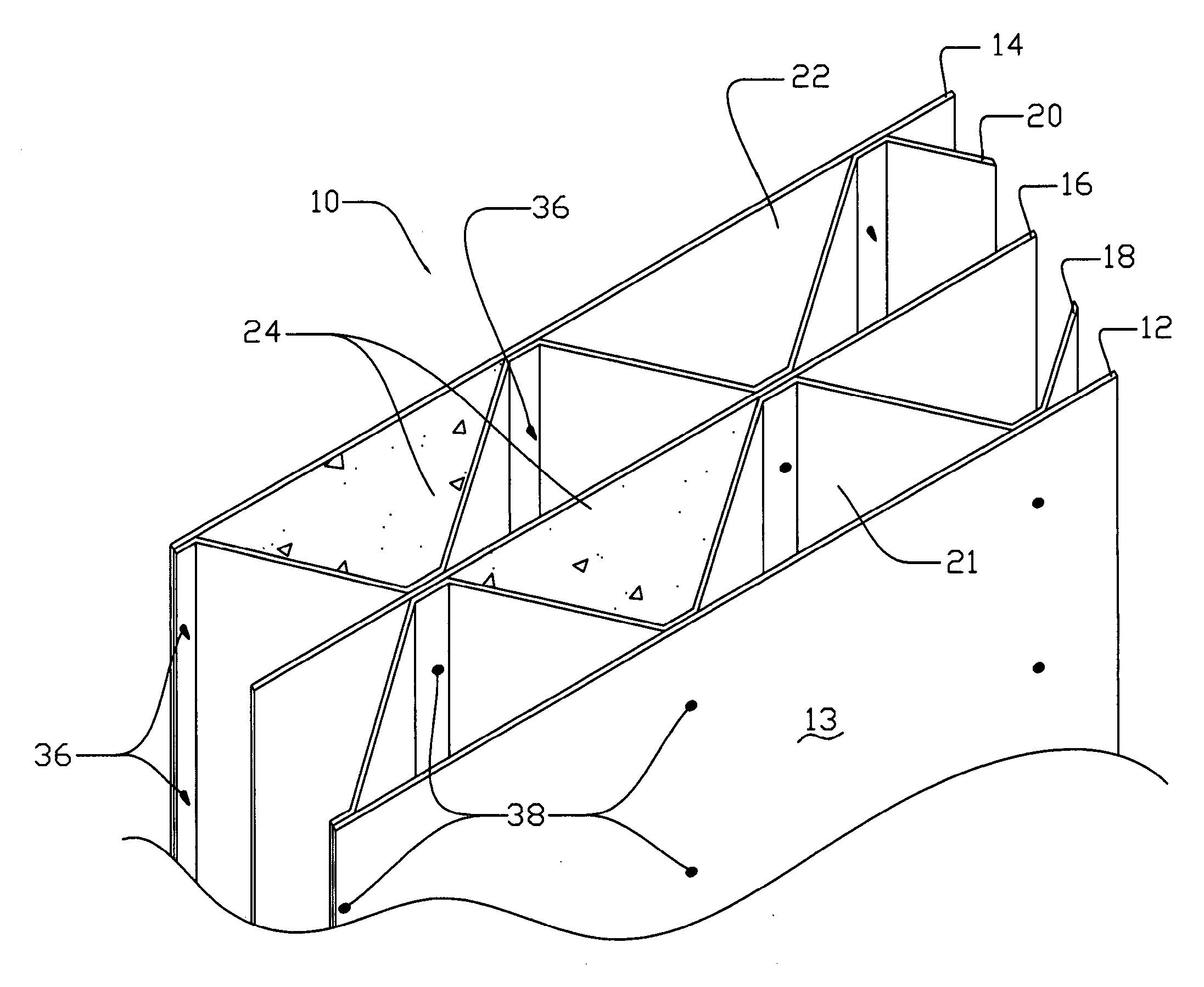
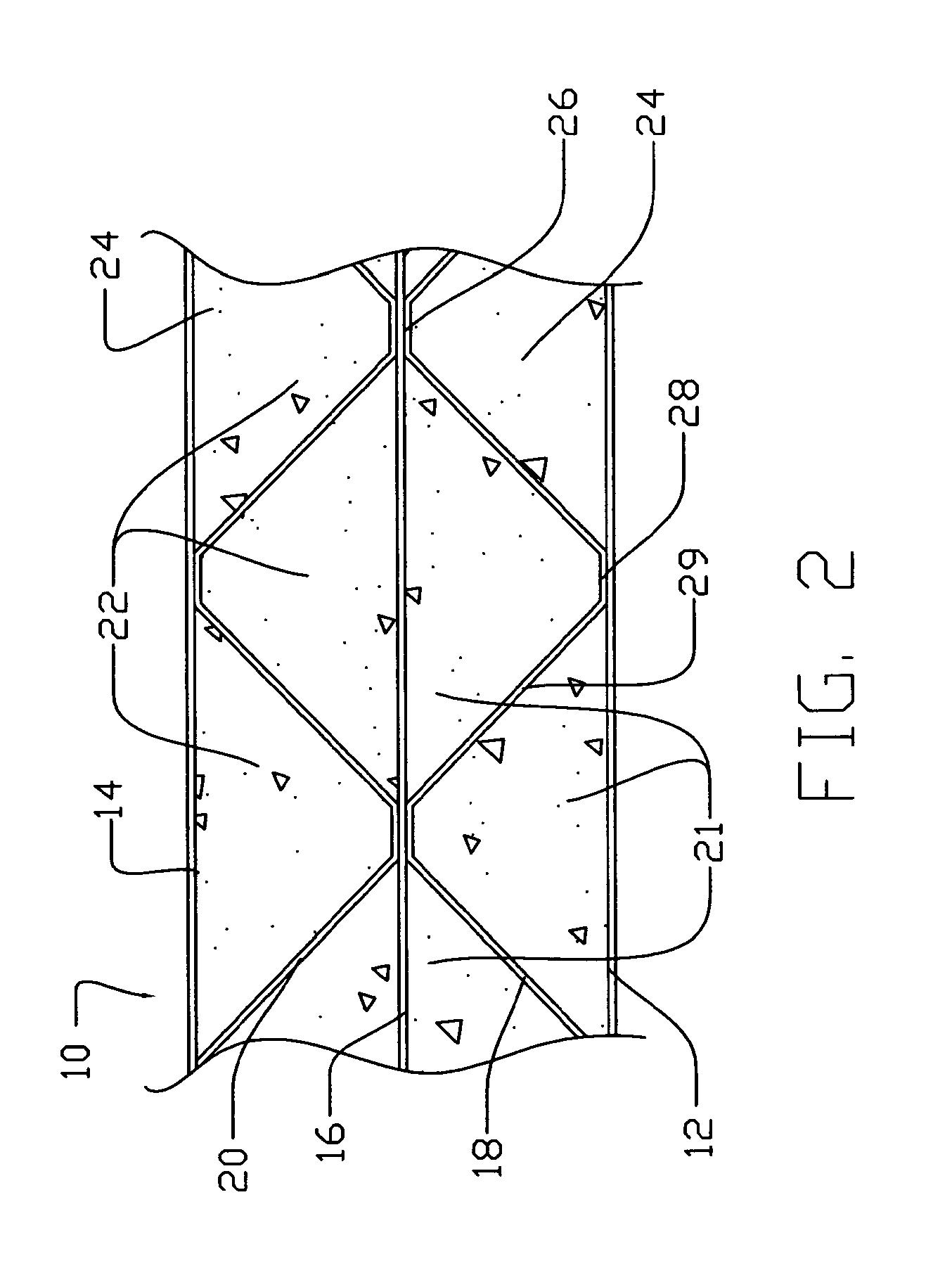
[0035]Referring now to FIGS. 1-3, there is shown a preferred embodiment of the present invention. As shown, a ballistic construction panel 10 includes an inner sheet member 12, an outer sheet member 14, and a middle sheet member 16. These sheets 12, 14, 16 are relatively thin, rigid, and planar and are disposed parallel to each other. A corrugated member is disposed between adjacent sheets. In the preferred embodiment, there are three sheets and therefore there are two corrugated members 18, 20. Corrugated member 18 is disposed between and abuts sheets 12 and 16 while corrugated member 20 is disposed between and abuts sheets 14 and 16. In this manner, a layered or sandwich arrangement is produced having alternating layers of a sheet, then a corrugated member, then a sheet, etc. By abutting the corrugated members 18, to the planar sheets 12-16 a plurality of enclosed cells or channels 21, 22 are formed within the panel 10. These cells 21, 22 are filled with a solid granular filler ma...


PUM

PropertyMeasurementUnit
angleaaaaaaaaaa
heightaaaaaaaaaa
thickaaaaaaaaaa

Abstract

A ballistic resistant construction panel having a series of elongated channels formed by coupling a corrugated member to adjacent planar wall members. These channels are filled with sand to provide the ballistic resistance of the panel. These panels are constructed of a fiber-reinforced plastic material and may be assembled together to form a temporary shelter.

Description

CROSS-REFERENCE TO RELATED APPLICATIONS[0001]This application is a continuation of U.S. application Ser. No. 11 / 374,542 entitled “BALLISTIC CONSTRUCTION PANEL”, filed on Mar. 11, 2006.FIELD OF THE INVENTION[0002]The present invention relates to structural panels used in construction and more particularly to ballistic resistant structural panels that can be assembled together to erect a shelter.BACKGROUND OF THE INVENTION[0003]Temporary shelters differ from traditional permanent buildings or structures in that a temporary shelter must be portable and relatively easy to construct. This is particularly true when the shelters must be constructed to provide housing for a large number of people in a short amount of time. For example, during a military deployment or an emergency situation where an area's housing may be destroyed or made uninhabitable.[0004]Additionally, conventional temporary shelters deployed in combat zones or other areas where violence may break out are often not resist...

Claims


Application Information

Patent Timeline
Patent Type & Authority Applications(United States)
IPC IPC(8): E04C2/32E04C2/34
CPCE04C2/22E04C2/3405E04C2002/345E04C2002/3455E04C2002/3472
Inventor HUGHES, JR., JOHN P.
Owner HUGHES JR JOHN P
Why Eureka
Try Eureka