
Diluting sampler and a method for collecting and diluting a gaseous sample

a sampler and gaseous sample technology, applied in the field of diluting sampler and a method for collecting and diluting gaseous sample, can solve the problems of dilution gas heating and other problems, and achieve the effect of preventing reducing the loss of sample material, and being convenient to us

Active Publication Date: 2010-07-29
DEKATI
View PDF17 Cites 11 Cited by
  • Summary
  • Abstract
  • Description
  • Claims
  • Application Information

AI Technical Summary

Benefits of technology

[0008]The objective of the invention is to alleviate the disadvantages referred to above. One specific objective of the invention is to achieve a novel diluting sampler that is simple in structure and efficiently prevents the losses of sample material. It is also an objective of the invention to disclose a novel method for collecting and diluting a gaseous sample, which method also efficiently prevents the losses of sample material.SUMMARY OF THE INVENTION

Problems solved by technology

In this manner, heat is allowed to be conducted from the sample space into the dilution gas space, which results in heating of the dilution gas.

Method used


Image

  • Diluting sampler and a method for collecting and diluting a gaseous sample
  • Diluting sampler and a method for collecting and diluting a gaseous sample
  • Diluting sampler and a method for collecting and diluting a gaseous sample

Examples


Embodiment Construction

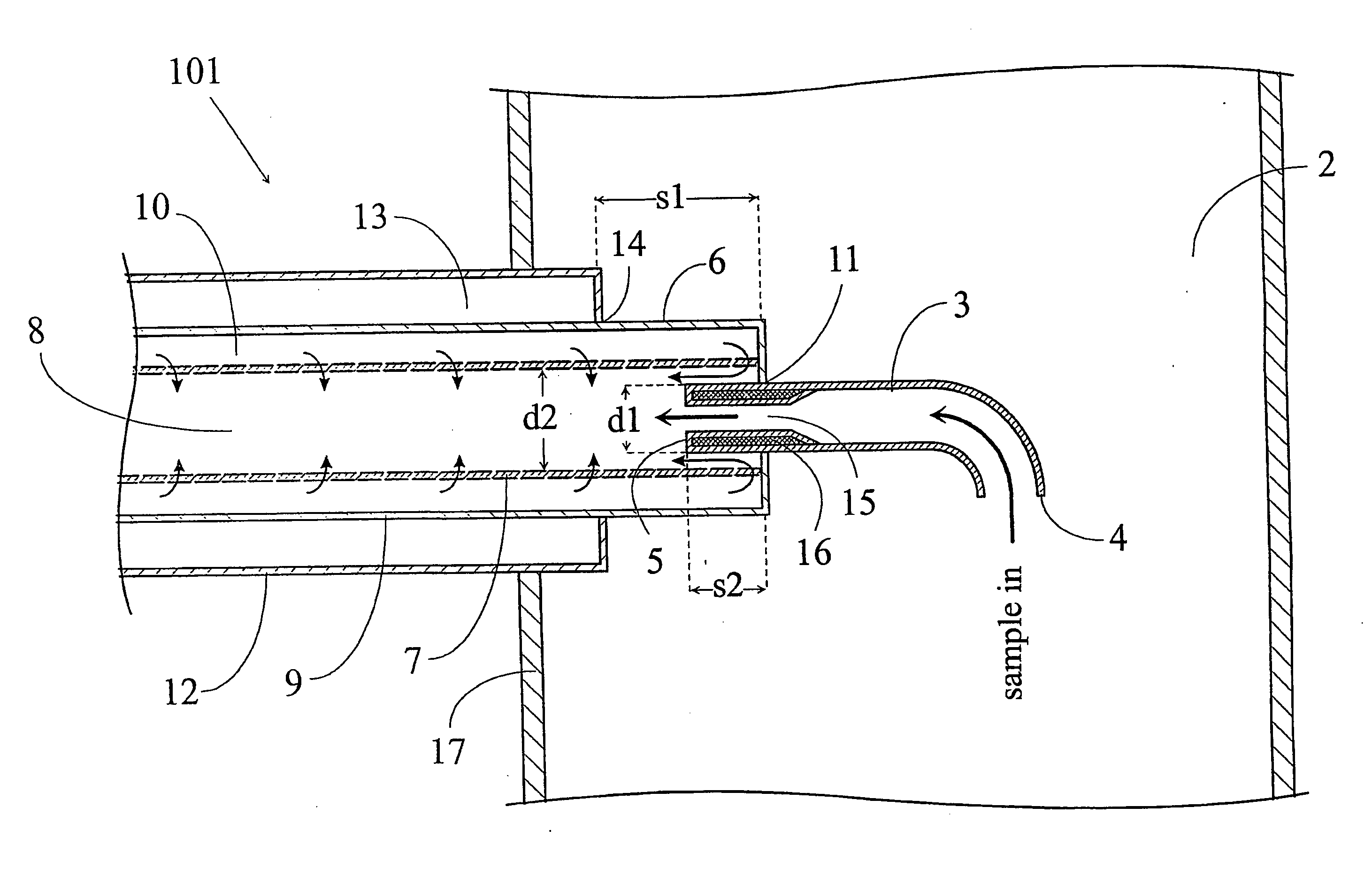
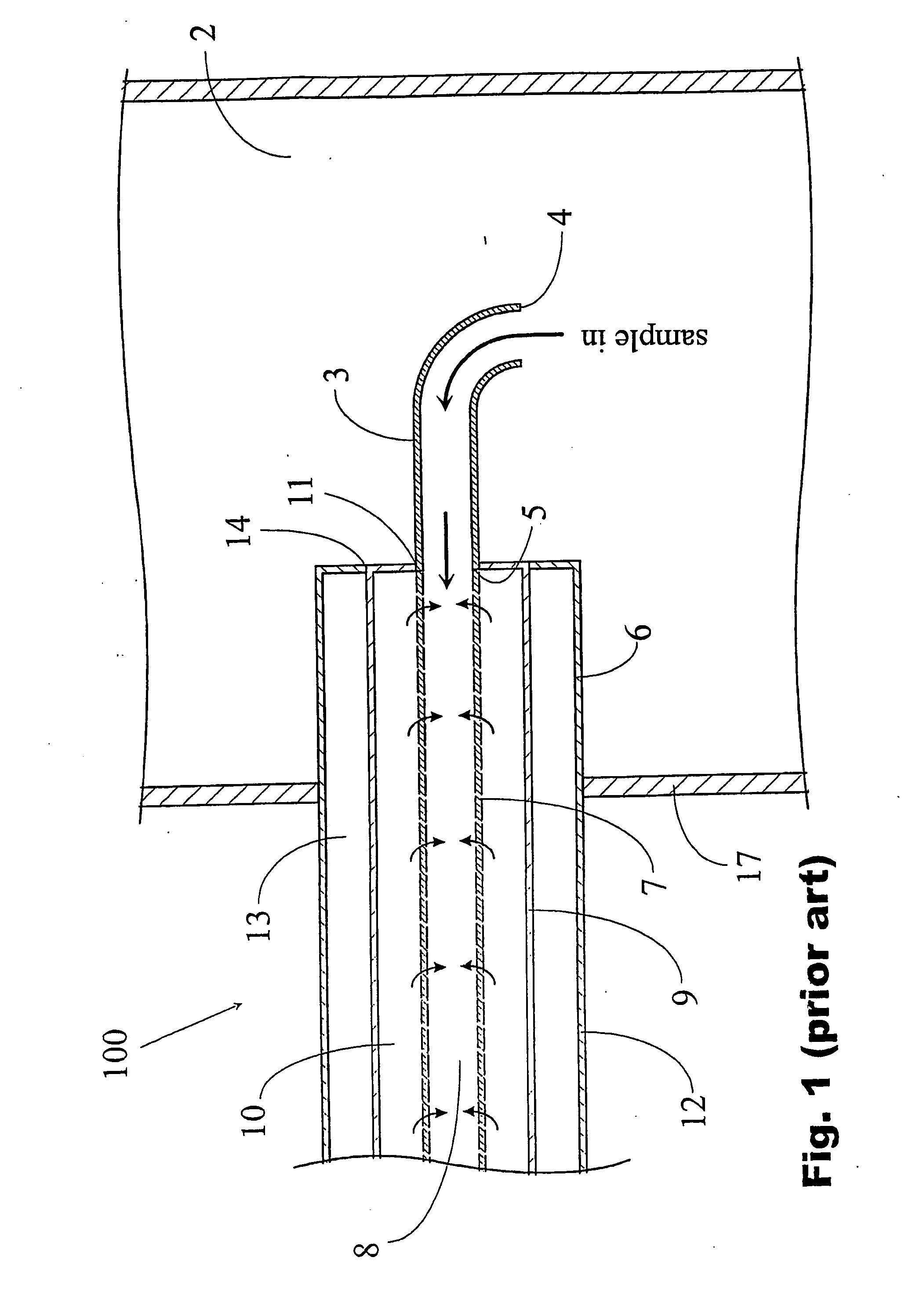
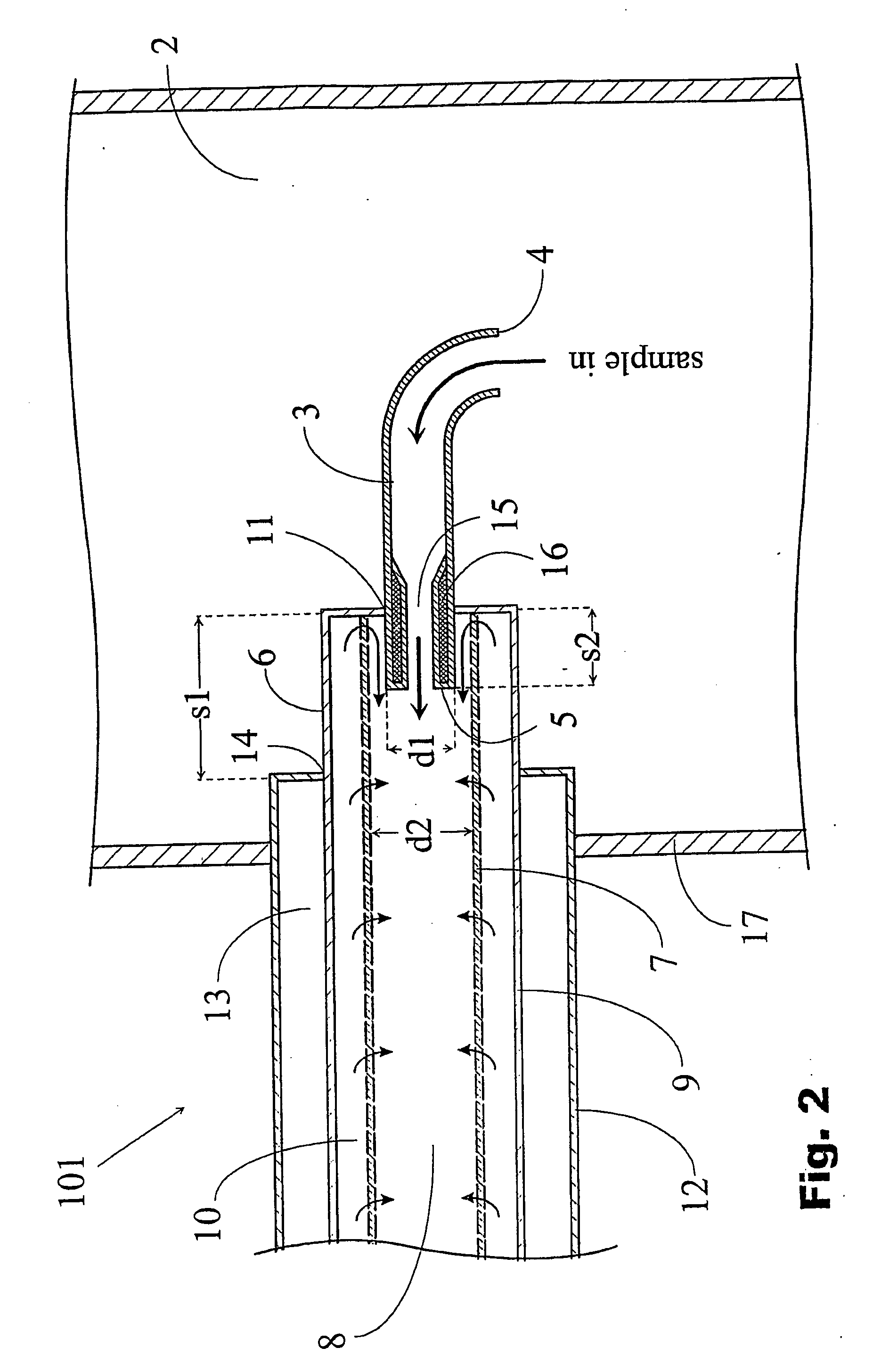
[0031]In order to facilitate the comparison, the corresponding parts of samplers 100, 101 of FIG. 1 (prior-art) and FIG. 2 (the invention) are denoted by the same reference numerals. Samplers 100, 101 presented in the figures in cross sections are installed to extend into a sample space 2, with a gaseous sample flowing therein. The next explanation concerns both samplers 100, 101, where appropriate. Sampler 100, 101 includes a sampling tube 3 having a first end 4 opening into the sample space 2 and a second end 5. In the vicinity of the first end 4, the sampling tube 3 is bent to be in parallel to the gas flow of the sample space to facilitate the introduction of the sample into the sampling tube. Sampler 100, 101 also includes a diluter 6 for receiving a flow of sample from the sampling tube 3 and for diluting the sample. The diluter 6 has a tubular porous first jacket 7, within which there is a sample channel 8, into which the second end of the sampling tube opens. The first jacke...


PUM

PropertyMeasurementUnit
outer diameteraaaaaaaaaa
inner diameteraaaaaaaaaa
distanceaaaaaaaaaa

Abstract

In the method, for collecting and diluting a gaseous sample disposed at a temperature substantially higher than the normal temperature from a sample space (2), a flow of sample is collected into a sampling tube (3); the flow of sample is introduced from the sampling tube into a sample channel (8) formed by a gas permeable first jacket (7); dilution gas is introduced into a dilution gas space (10) formed by a second jacket (9) enclosing the first jacket and connected by its end to the sampling tube, and further from it, through the first jacket into the sample channel; and heat is conducted from the sample space (2) into the dilution gas space (10) for warming up the dilution gas that comes into contact with the sampling tube (3). According to the invention, in the method, a substantially laminar protection flow, which encloses the flow of sample being released from the sampling tube (3) into the sample channel (8) and is disposed longitudinally to the sample channel, is formed from the warmed up dilution gas.

Description

FIELD OF THE INVENTION[0001]The present invention relates to the follow-up and monitoring of emissions produced by various combustion processes, such as by the reactors of power plants or the engines of vehicles. The invention relates to a diluting sampler for collecting a gaseous sample disposed at a temperature substantially higher than a normal temperature from a sample space. The invention also relates to a method for collecting a sample of the aforementioned kind from a sample space and for diluting it.BACKGROUND OF THE INVENTION[0002]The number and quality of gases and particles being released from combustion processes are analyzed in different ways, both because of environmental decrees and for the purposes of process regulation. From an analysis standpoint, some challenging characteristics are associated with combustion processes, one of the most significant ones being the temperature. For example, the internal temperature of a chimney of a power plant near the reactor can b...

Claims


Application Information

Patent Timeline
Patent Type & Authority Applications(United States)
IPC IPC(8): G01N1/22
CPCG01N2001/2264G01N1/2247
Inventor VESALA, HANNU
Owner DEKATI
Learn More