System and method for a flow sensor

a flow sensor and flow sensor technology, applied in the direction of instruments, liquid/fluent solid measurement, operating means/releasing devices of valves, etc., can solve the problems of expensive manufacturing and inaccurate and reliable flow sensors

Active Publication Date: 2010-07-29
GENERAL ELECTRIC CO
View PDF14 Cites 18 Cited by
  • Summary
  • Abstract
  • Description
  • Claims
  • Application Information

AI Technical Summary

Problems solved by technology

One problem with conventional ventilator systems is that such systems req

Method used


Image

  • System and method for a flow sensor
  • System and method for a flow sensor
  • System and method for a flow sensor

Examples


Embodiment Construction

[0016]In the following detailed description, reference is made to the accompanying drawings that form a part hereof, and in which is shown by way of illustration specific embodiments that may be practiced. These embodiments are described in sufficient detail to enable those skilled in the art to practice the embodiments, and it is to be understood that other embodiments may be utilized and that logical, mechanical, electrical and other changes may be made without departing from the scope of the embodiments. The following detailed description is, therefore, not to be taken as limiting the scope of the invention.

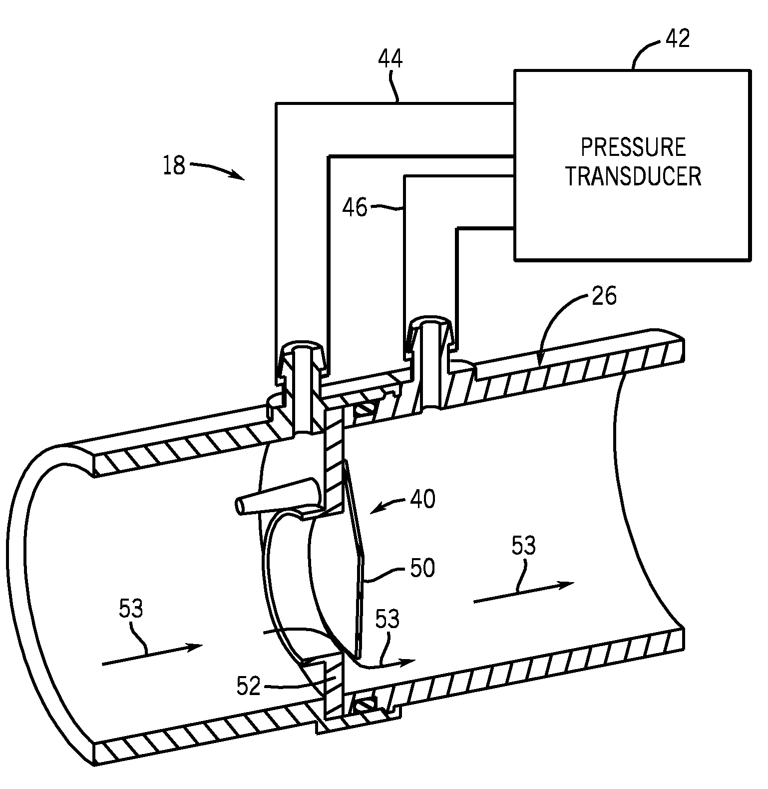
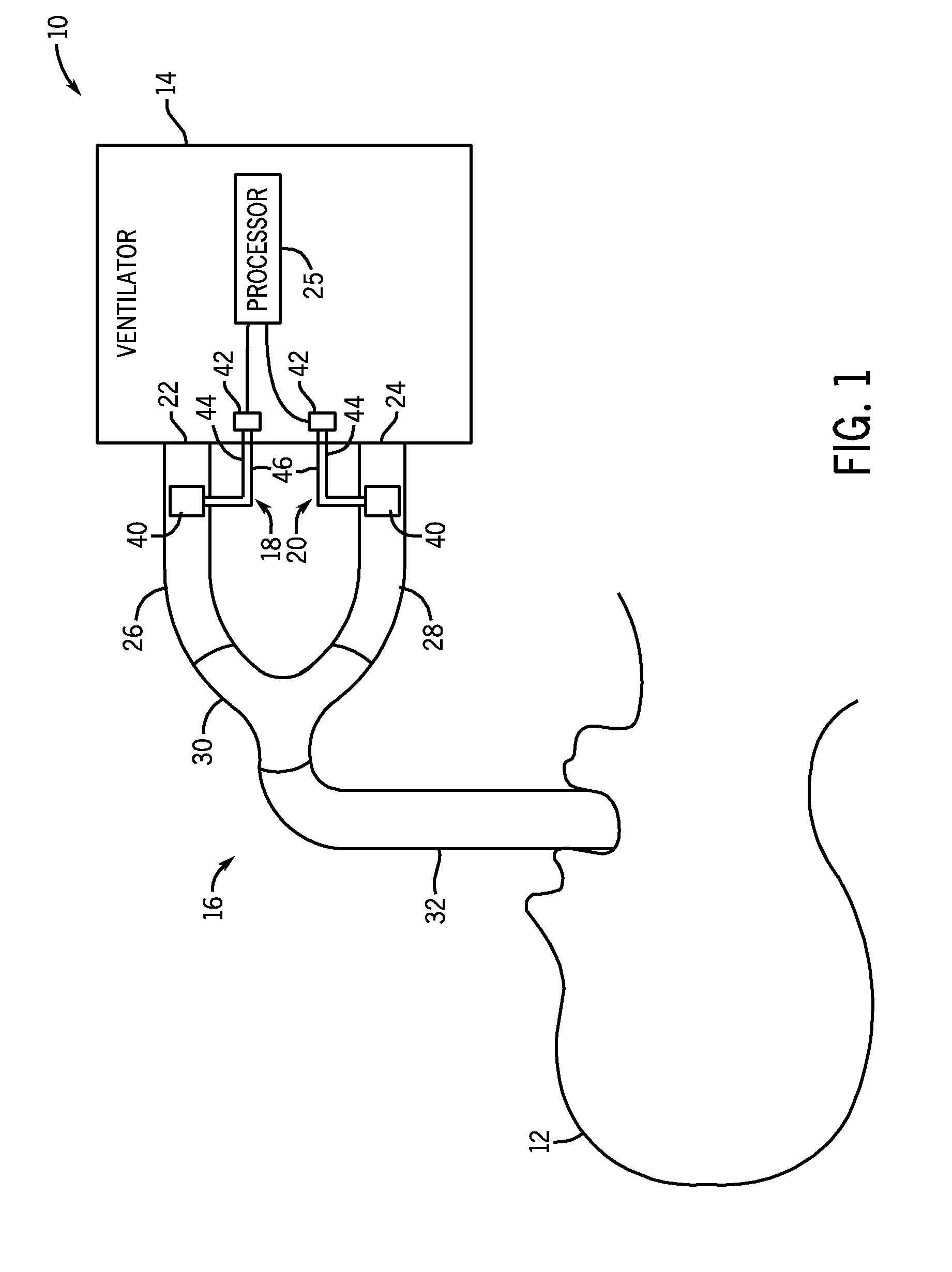
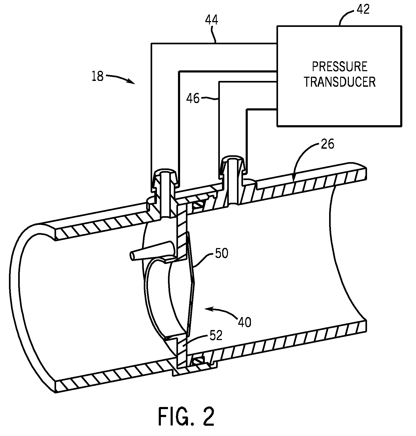
[0017]Referring to FIG. 1, a schematically illustrated ventilator system 10 is shown connected to a patient 12 in accordance with an embodiment. The ventilator system 10 includes a ventilator 14, a breathing circuit 16, an inspiratory flow sensor 18, and an expiratory flow sensor 20. The ventilator 14 includes an inspiratory connector 22, an expiratory connector 24, and a proc...


PUM


Abstract

A flow sensor for a medical ventilator system is disclosed herein. The flow sensor includes a valve assembly having a valve seat, and a valve flap attached to the valve seat. The valve flap is composed of an elastomeric material configured to generate a pre-load that biases the valve flap into engagement with the valve seat such that the valve assembly remains closed in the absence of an externally applied force. The flow sensor also includes a pressure transducer configure to measure a first pressure level at an upstream position relative to the valve assembly, and a second pressure level at a downstream position relative the valve assembly. The flow sensor also includes a processor configured to estimate the flow rate of a fluid passing through a medical ventilator system based on the first and second pressure levels.

Description

FIELD OF THE INVENTION[0001]This disclosure relates generally to system and method for a flow sensor that may be implemented in a medical ventilator system.BACKGROUND OF THE INVENTION[0002]Medical ventilator systems are used to provide respiratory support to patients undergoing anesthesia and respiratory treatment whenever the patient's ability to breath is compromised. The primary function of the medical ventilator is to maintain suitable pressure and flow of gases inspired and expired by the patient. Medical ventilator operation is commonly regulated based on feedback from one or more flow sensors. The flow sensors are generally disposed within or otherwise pneumatically coupled with a breathing circuit. One problem with conventional ventilator systems is that such systems require accurate and reliable flow sensors that are expensive to manufacture.BRIEF DESCRIPTION OF THE INVENTION[0003]The above-mentioned shortcomings, disadvantages and problems are addressed herein which will b...

Claims


Application Information

Patent Timeline
IPC IPC(8): A61M16/20
CPCA61M16/00A61M2016/0027A61M2016/0039A61M2016/0042A61M16/0833A61M16/0858A61M16/021
Inventor MASHAK, JAMES NYAL
Owner GENERAL ELECTRIC CO
Why Eureka
Try Eureka