Flow measurement and control with bubble detection

a flow measurement and control technology, applied in the direction of liquid/fluent solid measurement, process and machine control, instruments, etc., can solve the problems of spurious measurement, instability of the controlled flow, and the signal upon which the flow meter bases its flow measurement, so as to minimize the effect of the bubble effect and the stability of the liquid flow control

Inactive Publication Date: 2007-08-16
CELERITY
View PDF26 Cites 44 Cited by
  • Summary
  • Abstract
  • Description
  • Claims
  • Application Information

AI Technical Summary

Benefits of technology

[0008] Applicants have developed systems and methods for achieving stable operation of liquid flow controls even when a bubble passes through the sensor system. The systems and methods developed by applicants can minimize the effect of the bubble on liquid flow measurements or on controlled liquid flow rates.
[0009] In exemplary embodiments, a liquid flow sensor system of the present invention senses a flow signal indicative of the flow rate of the liquid flowing in a sensor conduit. The system analyzes the flow signal to determine, for example, by detecting characteristic changes in the signal, whether a bubble is present in the sensor co

Problems solved by technology

When a bubble enters a sensor conduit of any type of flow meter, the signal upon which the flow meter bases its flow measurement may be disturbed.
This can result in spurious measurements.
This can lead to instability in the controlled flow, which interferes with the purpose of the controller to provide a stable flow at a rate corresponding to a (typically user-set) setpoint.
Although the presence of bubbles can affect any type of flow meter or controller (and to varying degrees), it is especially problematic for ultra

Method used


Image

  • Flow measurement and control with bubble detection
  • Flow measurement and control with bubble detection
  • Flow measurement and control with bubble detection

Examples


Embodiment Construction

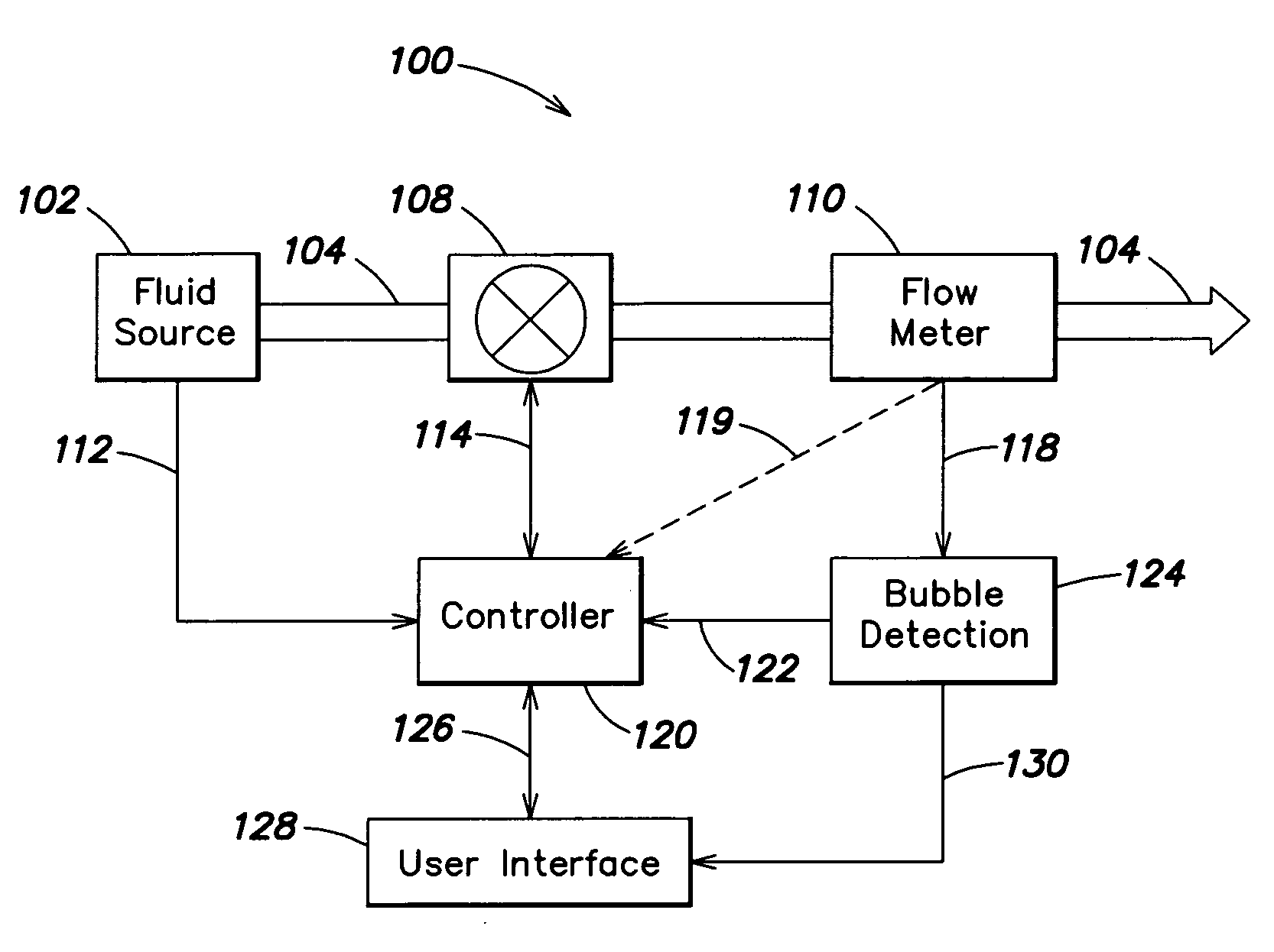
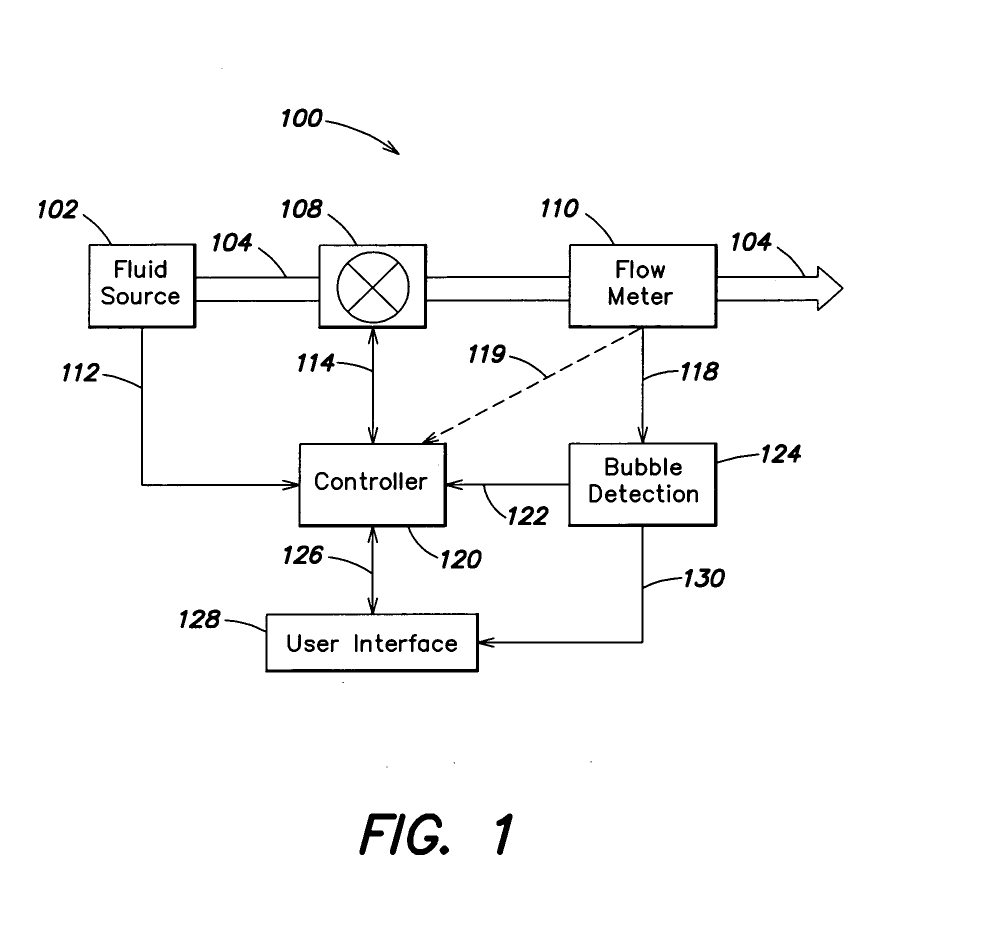
[0037] Referring to FIG. 1, there is illustrated a schematic block-diagram of one example of a liquid control system according to aspects of the present invention. The system 100 as illustrated includes a controllable valve 108 through which liquid flows, as indicated by line / arrow 104. It is to be appreciated that although the following discussion will refer primarily to element 108 being a controllable or variable valve, element 108 may also be another type of liquid actuator such as, for example, a pump. The valve 108 may be, for example, an electronically controlled variable valve that may be adjusted to vary the flow rate of the liquid through the system. The valve 108 is controlled by a controller 120 as indicated by line 114. The controller 120 may be, for example, a microprocessor-based controller. A liquid flow meter 110 may be positioned downstream of the valve 108, as shown. Alternatively, the liquid flow meter 110 may be disposed upstream of the valve 108. The flow of th...


PUM


Abstract

Systems and methods for liquid flow sensing and control for use with a variety of different types of liquid flow measurement and control systems. The liquid flow sensor system senses a flow signal indicative of the flow rate of the liquid flowing in a sensor conduit and analyzes the flow signal to determine, by detecting characteristic changes in the signal, whether a bubble is present in the sensor conduit. Where the system determines that a bubble is present, it may generate an alarm signal indicative of the presence of the bubble. A flow control system incorporating the flow sensor as a feedback source may respond to the detection of a bubble by temporarily freezing the flow control parameters until the bubble has exited the sensor conduit. The flow control system can implement procedures for clearing a bubble from the sensor conduit where the system detects that the bubble has become stuck.

Description

CROSS REFERENCE TO RELATED APPLICATIONS [0001] This application claims priority under 35 U.S.C. § 119(e) to U.S. Provisional Patent Application No. 60 / 707,628, filed Aug. 12, 2005, entitled “Bubble Algorithm Design,” which is incorporated herein by reference in its entirety.BACKGROUND OF THE INVENTION [0002] 1. Field of Invention [0003] The present invention relates to systems and methods for measuring and controlling liquid flow, and more specifically to systems and methods for measuring and controlling liquid flow in environments where bubbles may be present in the liquid flow. [0004] 2. Discussion of Related Art [0005] Several techniques exist for measuring a flow rate of a liquid flowing in a conduit, pipe, or tube. These include thermal flow meters, coriolis force flow meters, differential pressure flow meters, and ultrasonic flow meters. Generally, liquid flow meters sense one or more parameters of the flow that can be calibrated to correspond to the rate (e.g., volumetric or ...

Claims


Application Information

Patent Timeline
IPC IPC(8): G05D7/00
CPCG01F1/667G01F1/74G01F25/0007G05D7/0635G01P5/245G01P5/247G01N2291/02836G01F25/10G01F1/66G01F25/00G01F1/00
Inventor DUAN, HAOTINT, AARON S.ELLEC, CHRISTOPHE
Owner CELERITY
Why Eureka
Try Eureka