Combined Pressure and Flow Sensor Integrated in a Shunt System

a flow sensor and shunt technology, applied in the field of combined pressure and flow sensors, can solve the problems of limited clinical use of existing sensors, limited extended use of pressure sensors, and discontinued commercial distribution of such pressure sensors

Inactive Publication Date: 2009-08-13
MEDOS INT SARL
View PDF8 Cites 42 Cited by
  • Summary
  • Abstract
  • Description
  • Claims
  • Application Information

AI Technical Summary

Problems solved by technology

To help measure the pressure of the CSF, a limited number of pressure sensors have been developed that can be integrated directly into the shunt systems, but the commercial distribution of such pressure sensors has since been discontinued.
Clinical use of existing sensors has been limited by the following factors: size of the sensor housing, complexity of the interrogation procedure, complexity of the implantation procedure, stability of the sensor reading with time, and lifetime of the sensor.
These shortcomings have limited their extended use in a clinical setting.
Its main limitation is the complexity of the reading process, and also the fact that it relies on a pressurization of the sensor through an external cuff.
This factor also limits the use of the sensor for short term measureme

Method used


Image

  • Combined Pressure and Flow Sensor Integrated in a Shunt System
  • Combined Pressure and Flow Sensor Integrated in a Shunt System
  • Combined Pressure and Flow Sensor Integrated in a Shunt System

Examples


Embodiment Construction

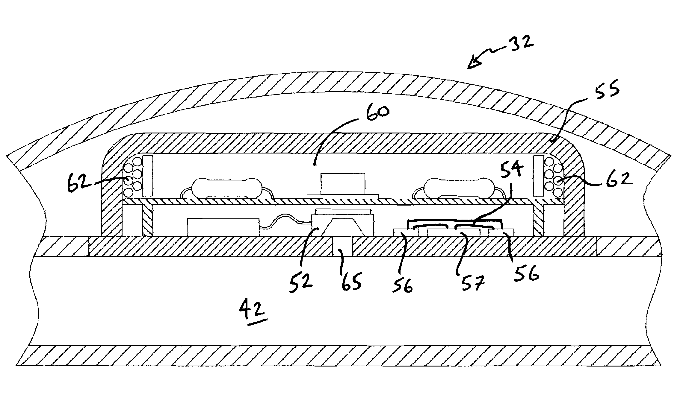
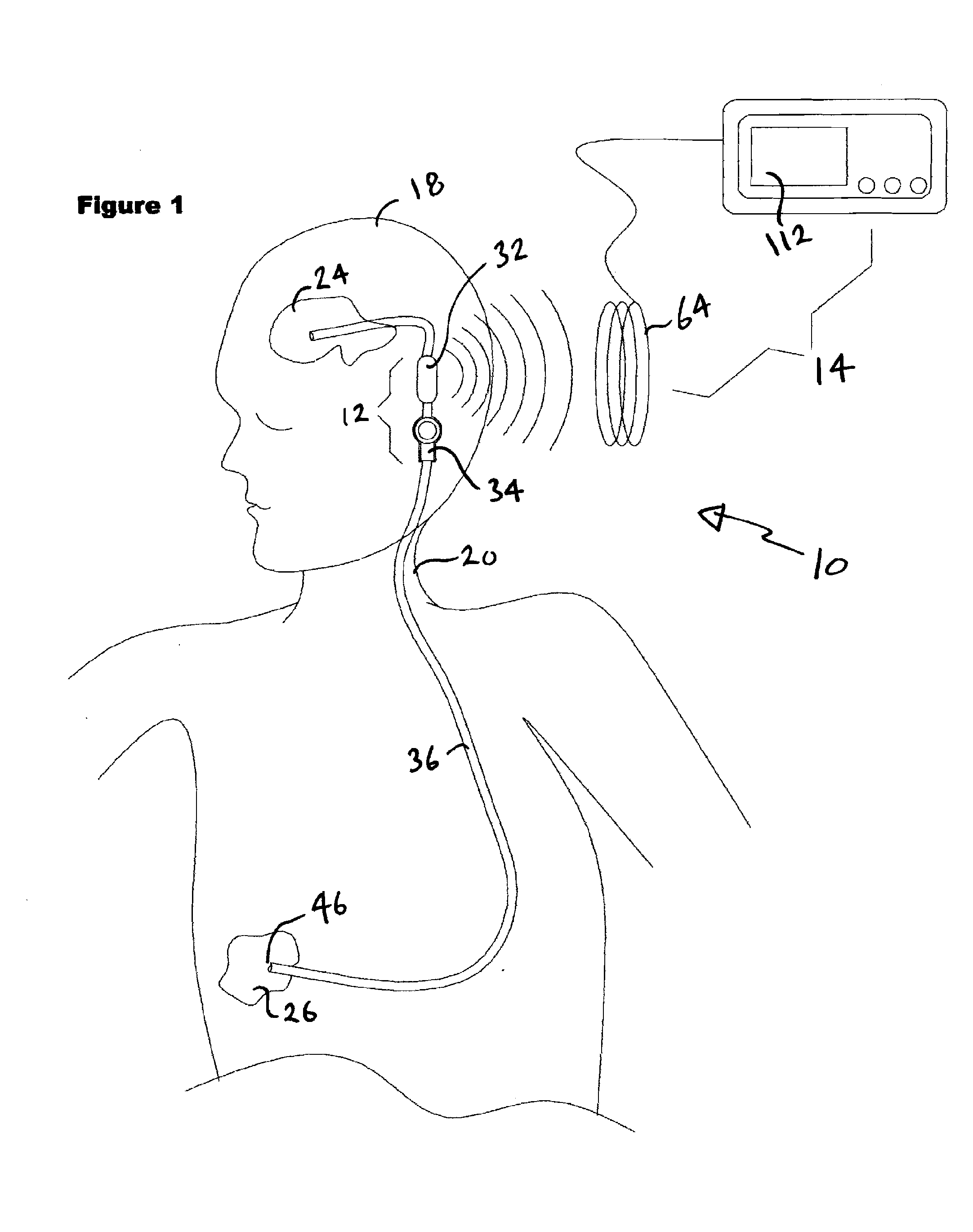
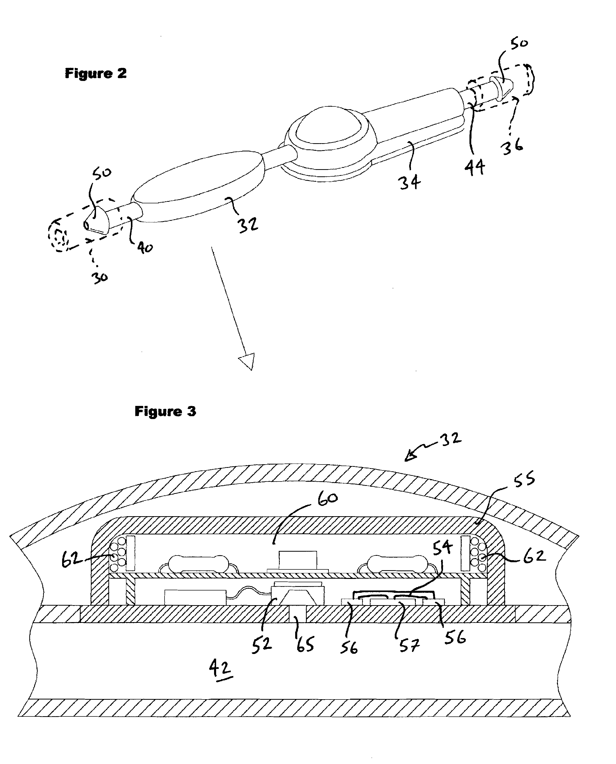
[0045]By way of overview and introduction, the present invention concerns improvements in the shunt that is used as part of a hydrocephalus treatment therapy to divert excess fluid from the lateral ventricles of a patient's brain to a diversion site located elsewhere in the patient's body. As mentioned above in the background section of this patent application, it would be desirable to be able to measure on demand both the pressure and the rate of flow of the CSF within such a fluid-diverting system. It has been shown above that a parameter called “brain compliance” might be a useful value in determining the overall success of the therapy used to treat the patient's hydrocephalus condition and that this parameter can be calculated if the CSF pressure, instantaneous flow rate and steady state flow rate are both known. To this end, the improved shunt of this invention allows for a non-invasive real-time measurement of all three of these parameters. When used together with a reader, fu...


PUM


Abstract

A shunt system for implantation into a patient for diverting excess fluid from the lateral ventricles of the patient's brain to a diversion site. The present shunt includes a pressure transducer for measuring ICP, a rate of flow transducer for measuring the flow rate of the CSF flowing within the shunt, and telemetry circuitry. A remote reader with an antenna is provided to selectively interrogate and provide inductive power to the implanted shunt. Upon interrogation, the pressure and rate of flow measurements are calibrated, multiplexed and transmitted on a carrier signal back to the remote reader/antenna. The reader/antenna extracts the pressure and flow rate data from the carrier wave and further separates the data by demultiplexing the signal. The reader further includes a barometer for providing local barometric pressure and uses this information together with the data from the implanted transducers to calculate and display real-time adjusted ICP, CSF flow-rate within the shunt and brain compliance.

Description

BACKGROUND OF THE INVENTION[0001]1. Field of the Invention[0002]The present invention generally relates to devices used in the treatment of hydrocephalus, and more particularly, to improvements to sensors and shunts used to help divert and monitor excess fluid during the treatment therapy.[0003]2. Description of the Related ArtBackground:[0004]The human brain includes four ventricles. Each ventricle contains a choroid plexus that produces cerebrospinal fluid (CSF) which bathes and cushions the brain and spinal cord within their bony and nonelastic confines.[0005]In a normal healthy person, CSF continuously circulates through and around the brain and its ventricles and around the spinal cord and is continuously drained away into the circulatory system so that a controlled pressure is continually maintained within the system. The CSF flows from the lateral ventricles via the foramina of Monro into the third ventricle, and then the fourth ventricle via the cerebral aqueduct in the brai...

Claims


Application Information

Patent Timeline
IPC IPC(8): A61B5/05A61M1/00
CPCA61B5/031A61M2205/3331A61M27/006
Inventor GINGGEN, ALECTARDY, YANIK
Owner MEDOS INT SARL
Why Eureka
Try Eureka