Pressure flow sensor systems and pressure flow sensors for use therein

a technology of flow sensor and pressure sensor, which is applied in the field of flow sensor and system, can solve the problems of sensor measurement susceptible to error and instability, sensor not particularly well suited to such applications, and uncontrolled changes in thermal response, etc., and achieves low cost, low power flow, and easy disposal

Active Publication Date: 2006-07-06
HONEYWELL INT INC
View PDF18 Cites 45 Cited by
  • Summary
  • Abstract
  • Description
  • Claims
  • Application Information

AI Technical Summary

Benefits of technology

[0018] Adjusting the calibration component, by trimming or otherwise, on the pressure sensing device instead of on the interrogation / signal conditioning circuit board or other associated electronics is advantageous in that the calibrated pressure sensing device including the calibration capacitor can be disposed of after use without having to dispose of associated interrogation / signal conditioning electronics.
[0019] The pressure flow sensor can therefore be implemented as a low cost and low power flow sensor which can be disposed of easily without having to replace costly electronics. The pressure flow sensor can be implemented in medical applications, such as in an intravenous drip system to measure the flow of liquid in the flow tube of the drip system. Wirelessly connecting the flow sensor to medical treatment apparatus without connecting wires or connectors enables an operator to manipulate the apparatus more easily.

Problems solved by technology

Typical flow sensors are not particularly well suited to such applications by virtue of the relatively high number of component parts, expensive materials and / or processing requirements, and high number of manufacturing-processing steps required to both produce the sensors and to integrate them into the instrumentation or apparatus of the application.
Such thermal flow sensors suffer from a variety of drawbacks For example, the open nature of the microbridge structure can result in condensates from vapor being retained in the microbridge structure leading to uncontrolled changes in thermal response making the sensor measurements susceptible to error and instability.
Furthermore, wires bonded to the heater and sensing elements retain particles suspended in the fluid and increase turbulence shifting flow response.
Also, the wires are prone to damage in a high mass flux environment and during cleaning of the sensor.
Thermal flow sensors are high power consumption devices where are costly to replace and, as such, unsuitable for use as disposable flow sensors in medical and other applications.
Furthermore, manipulation of the medical apparatus by an operator is made particularly cumbersome by the fact that flow sensors and other associated devices have to be connected to the apparatus using a variety of wires and connectors.

Method used


Image

  • Pressure flow sensor systems and pressure flow sensors for use therein
  • Pressure flow sensor systems and pressure flow sensors for use therein
  • Pressure flow sensor systems and pressure flow sensors for use therein

Examples


Embodiment Construction

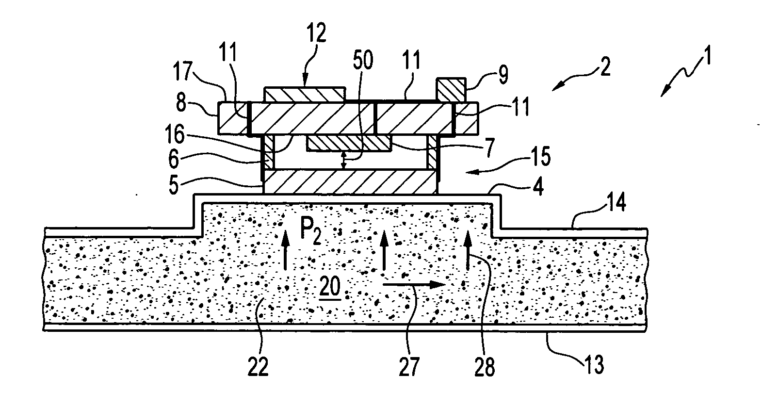
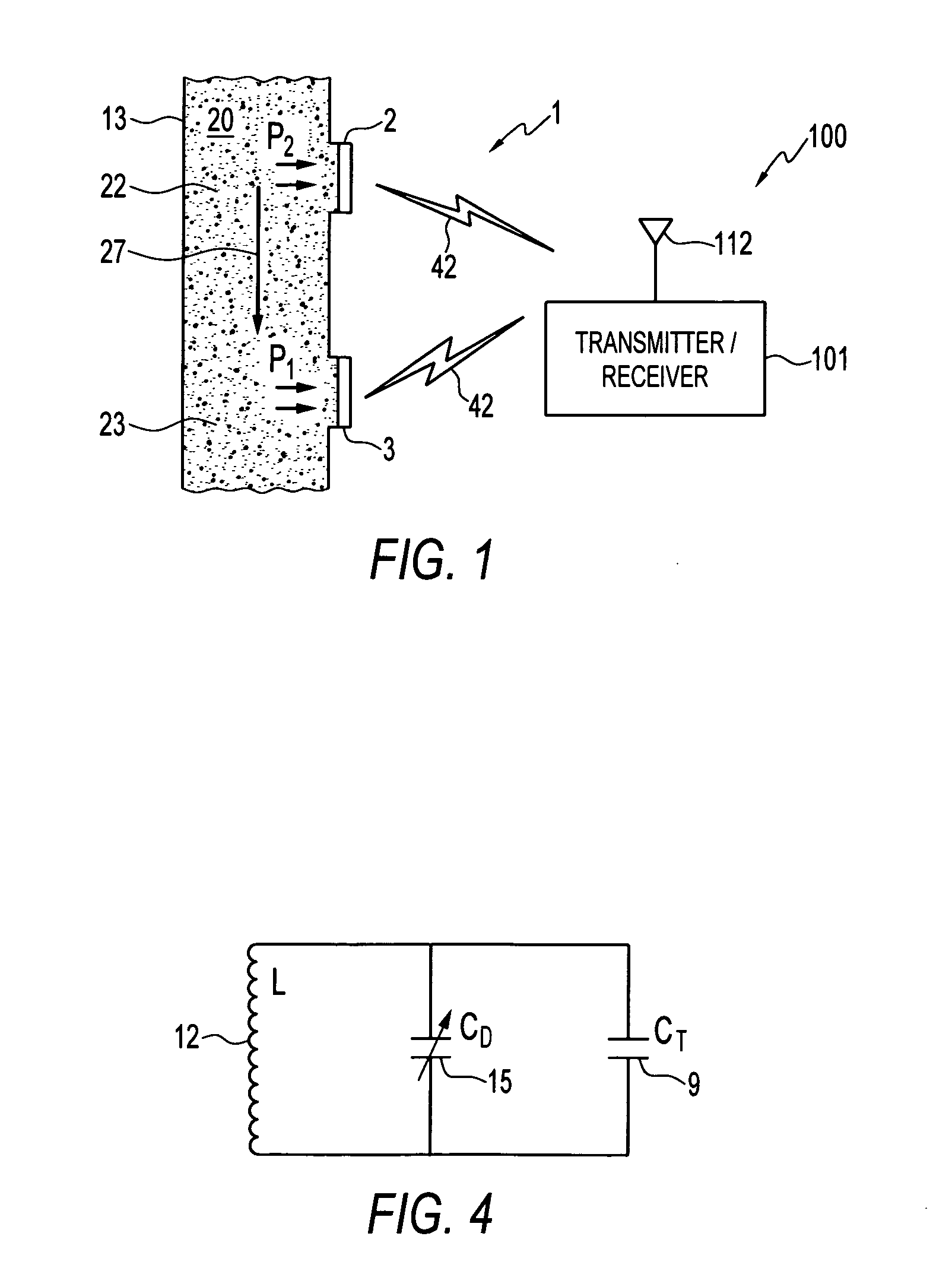
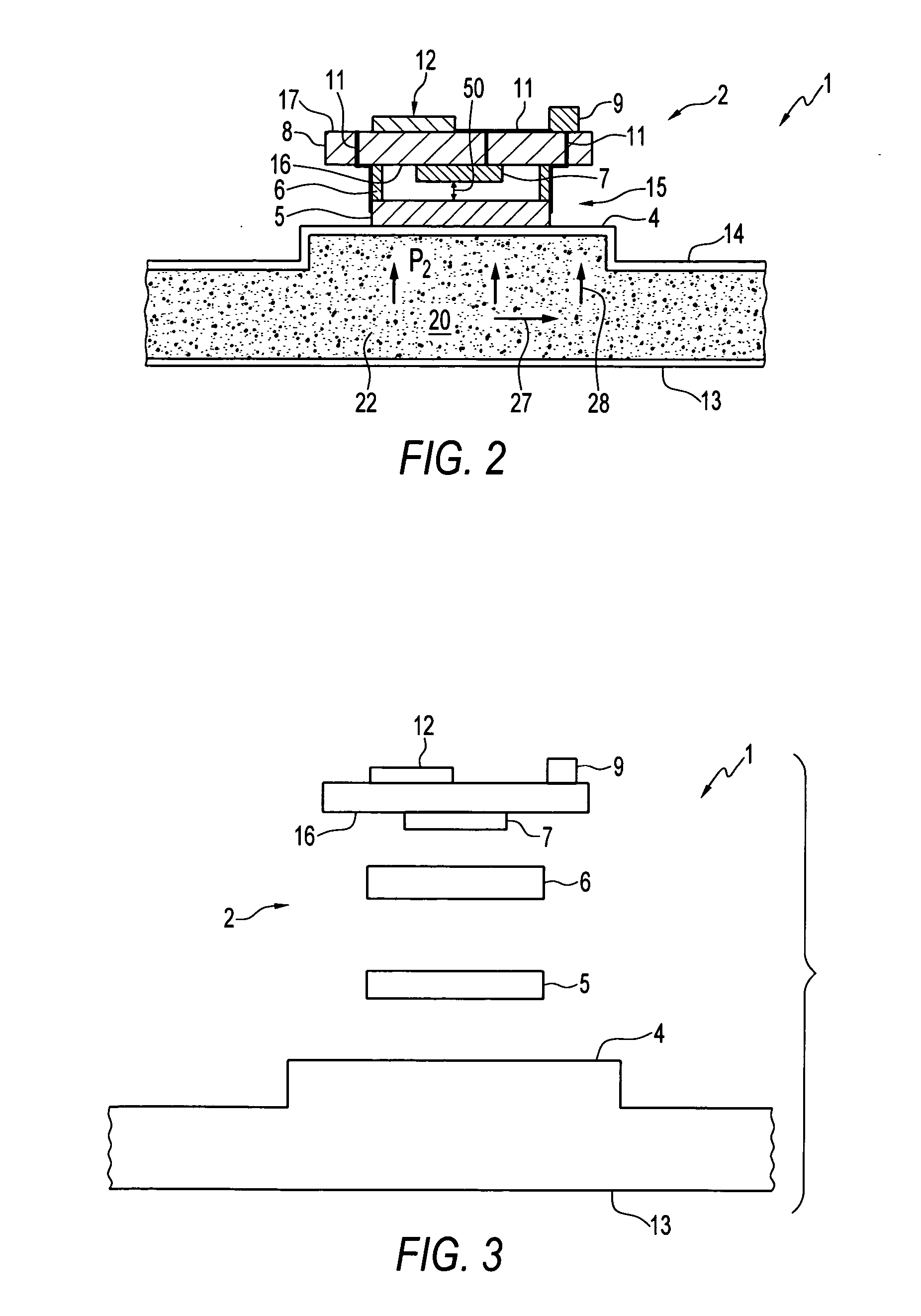
[0039] Referring to FIG. 1 of the accompanying drawings, which illustrates a side view of a pressure flow sensor system for sensing fluid flow in a channel in accordance with an embodiment, the pressure flow sensor system 100 has a pressure flow sensor 1 which is configured as a differential pressure flow sensor which has an upstream pressure sensing device 2 and a downstream sensing device 3 for detecting the flow rate of fluid 20 flowing through a channel 13 in the direction indicated by arrow 27. Upstream pressure sensing device 2 is operatively coupled to the channel 13 at upstream location 22 for detecting fluid pressure P2 whereas downstream pressure sensing device 3 is operatively coupled to channel 13 at downstream location 23 for detecting fluid pressure P1. As will be explained in more detail below, pressure sensing devices 2, 3 are configured to transmit and receive data to and from a transmitter / receiver 101 which includes an antenna 112. The wireless transmission of suc...


PUM

PropertyMeasurementUnit
diameteraaaaaaaaaa
pressureaaaaaaaaaa
inductanceaaaaaaaaaa

Abstract

A differential pressure flow sensor system comprises a disposable flow sensor which has upstream and downstream pressure sensing devices for detecting a differential pressure in a flow channel. Each sensing device comprises a diaphragm, a capacitor and an inductor electrically coupled to the capacitor so as to form an LC tank circuit. The capacitor and/or inductor can be mechanically coupled to the diaphragm such that a deflection of the diaphragm in response to fluid pressure applied thereto causes a change in the resonant frequency of the LC tank. The differential pressure and flow rate can be determined by detecting changes in the resonant frequency using interrogation electronics which can wirelessly interrogate the devices. A calibration capacitor and/or inductor can be formed on each sensing device and trimmed thereon for calibration purposes. Such pressure flow systems can be implemented in medical applications.

Description

CROSS-REFERENCE TO RELATED PATENT APPLICATION [0001] This patent application is a Continuation-in-Part (CIP) of U.S. patent application Ser. No. 11 / 002,409, entitled “Disposable and Trimmable Wireless Pressure Sensor for Medical Applications,” which was filed on Dec. 2, 2004 and is incorporated herein by reference.TECHNICAL FIELD [0002] Embodiments are generally related to sensors and sensing applications and, more particularly, to flow sensors and systems. Embodiments are additionally related to pressure flow sensor systems for use in medical and other applications. Additionally, embodiments are related to disposable pressure flow sensors for use in such systems and methods of manufacturing such pressure flow sensors and systems. BACKGROUND [0003] In single-use type applications, such as for example medical systems and instrumentation, discrete disposable sensors are required which can be implemented in a cost-effective manner. Typical flow sensors are not particularly well suited ...

Claims


Application Information

Patent Timeline
Patent Type & Authority Applications(United States)
IPC IPC(8): G01L9/00
CPCA61B5/02152A61B5/031G01F1/34G01L9/007G01L9/0072G01L9/10G01L9/12
Inventor LIU, JAMES ZT
Owner HONEYWELL INT INC
Why Eureka
Try Eureka