Subsea pipeline leakage monitoring system

A technology for monitoring systems and submarine pipelines, applied in the field of monitoring systems, can solve the problems of expensive real-time model monitoring, easy damage to submarine pipelines, and difficult transformation, and achieve the effect of low cost, low price and easy access

Active Publication Date: 2015-10-14
CHINA NAT OFFSHORE OIL CORP +1
View PDF6 Cites 42 Cited by
  • Summary
  • Abstract
  • Description
  • Claims
  • Application Information

AI Technical Summary

Problems solved by technology

Existing foreign submarine pipeline leakage monitoring methods mainly include pressure point analysis method, optical fiber method and real-time model. Among them, the monitoring results of pressure point analysis method are greatly affected by the instrument, and the optical fiber method requires the transformation of the submarine pipeline, and the transformation is difficult. Large, easily damaged subsea pipelines, real-time model monitoring is expensive and expensive

Method used


Image

  • Subsea pipeline leakage monitoring system
  • Subsea pipeline leakage monitoring system

Examples


Embodiment Construction

[0014] The present invention will be described in detail below in conjunction with the accompanying drawings and embodiments.

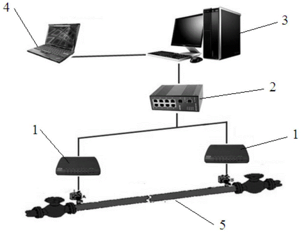
[0015] Such as figure 1 As shown, the submarine pipeline leakage monitoring system provided by the present invention can monitor the leakage of submarine single-phase flow pipelines and natural gas pipelines, wherein all the single-phase flow pipelines are gas, and the volume content of liquid natural gas in the natural gas pipelines does not exceed 10 %, it includes two controllers 1, two flow sensors, two pressure sensors, two temperature sensors, an Ethernet switch 2, a central host computer 3 and several remote monitoring devices 4.

[0016] The inlet and outlet of the pipeline 5 to be monitored are provided with a flow sensor, a pressure sensor and a temperature sensor, and the flow sensor, pressure sensor and temperature sensor at the inlet of the pipeline 5 to be monitored are used to collect flow, pressure and temperature signals at the inlet ...


PUM


Abstract

The invention relates to a subsea pipeline leakage monitoring system. The subsea pipeline leakage monitoring system comprises controllers, flow sensors, pressure sensors, temperature sensors and a center host computer. The inlet end and the outlet end of a pipeline to be monitored are each provided with one flow sensor, one pressure sensor and one temperature sensor. The flow sensor, the pressure sensor and the temperature sensor at the inlet end collect the flow, pressure and temperature signals of the inlet end in real time and send the flow, pressure and temperature signals to the first controller. The flow sensor, the pressure sensor and the temperature sensor at the outlet end collect the flow, pressure and temperature signals of the outlet end in real time and send the flow, pressure and temperature signals to the second controller. The controllers send the signals to the center host computer through an Ethernet switch, the leakage monitoring system inside the center host computer displays the information in real time and judges where the pipeline to be monitored is leaked or not, a leakage alarm is given out when leakage happens, and the leakage amount and leakage position are worked out and displayed. The center host computer sends the received signals and the judgment result to remote monitoring devices.

Description

technical field [0001] The invention relates to a monitoring system, in particular to a submarine pipeline leakage monitoring system. Background technique [0002] With the continuous increase of submarine pipelines, submarine pipelines have gradually become the lifeline of offshore oil and gas. Due to the complex submarine environment, submarine pipelines are prone to aging and corrosion, resulting in leakage of submarine pipelines. On the one hand, leakage of submarine pipelines will pollute the environment, on the other hand, it will cause economic losses, and more seriously, it will cause casualties. Therefore, the monitoring of submarine pipeline leakage has become an increasingly urgent technical problem to be solved. [0003] There are many researches on land pipeline leakage monitoring technology in China, the main methods are negative pressure wave method and acoustic wave method, because negative pressure wave method and acoustic wave method are highly sensitive t...

Claims


Application Information

Patent Timeline
Patent Type & Authority Applications(China)
IPC IPC(8): F17D5/02
Inventor 姚海元李清平白勇公彦蒙翁晓霞程兵庞维新王凯秦蕊
Owner CHINA NAT OFFSHORE OIL CORP
Why Eureka
Try Eureka