Pick and place device with automatic pick-up-height adjustment and a method and a computer program product to automatically adjust the pick-up-height of a pick and place device

a pick-up and place head technology, applied in the direction of manufacturing tools, instruments, transportation and packaging, etc., can solve the problems of inaccurate positioning, large errors, and use of vacuum supply leads to wrong detection points, so as to avoid any down time of the pick-up head and achieve fast results

Active Publication Date: 2015-10-22
KLA TENCOR TECH CORP
View PDF7 Cites 46 Cited by
  • Summary
  • Abstract
  • Description
  • Claims
  • Application Information

AI Technical Summary

Benefits of technology

[0013]It therefore is an object of the invention to provide a pick and place device with pick-up-height adjustment which can be done fast in a reliable and reproducible manner, so that a damage of a component in a production process by the pick and place head and any down time of the pick and place head are avoided.

Problems solved by technology

The visual estimation often leads to inaccurate positions due to difficult accessibility of the pickers.
Mostly the pickers are close to the devices and the assembly that carries the pickers blocks the visibility.
In most cases, safety doors and other assemblies are blocking light to access the area where the visual check is needed.
Assessing the correct contact point visually depends on the human capabilities (vision accuracy) so larger errors are common.
Using the vacuum supply leads to wrong detection points in case of medium and small devices.
The devices can be sucked up by the vacuum, leading to a wrong detection position of the contact.
This is very hard to calibrate since the pickup adapter can differ in height after a changeover.
In addition, using a displacement sensor or any other vision system is detrimental to the cost effectiveness.

Method used


Image

  • Pick and place device with automatic pick-up-height adjustment and a method and a computer program product to automatically adjust the pick-up-height of a pick and place device
  • Pick and place device with automatic pick-up-height adjustment and a method and a computer program product to automatically adjust the pick-up-height of a pick and place device
  • Pick and place device with automatic pick-up-height adjustment and a method and a computer program product to automatically adjust the pick-up-height of a pick and place device

Examples


Embodiment Construction

[0061]In the figures like reference numerals are used for like elements or elements of like function. Furthermore, for the sake of clarity, only those reference numerals are shown in the figures which are necessary for discussing the respective figure.

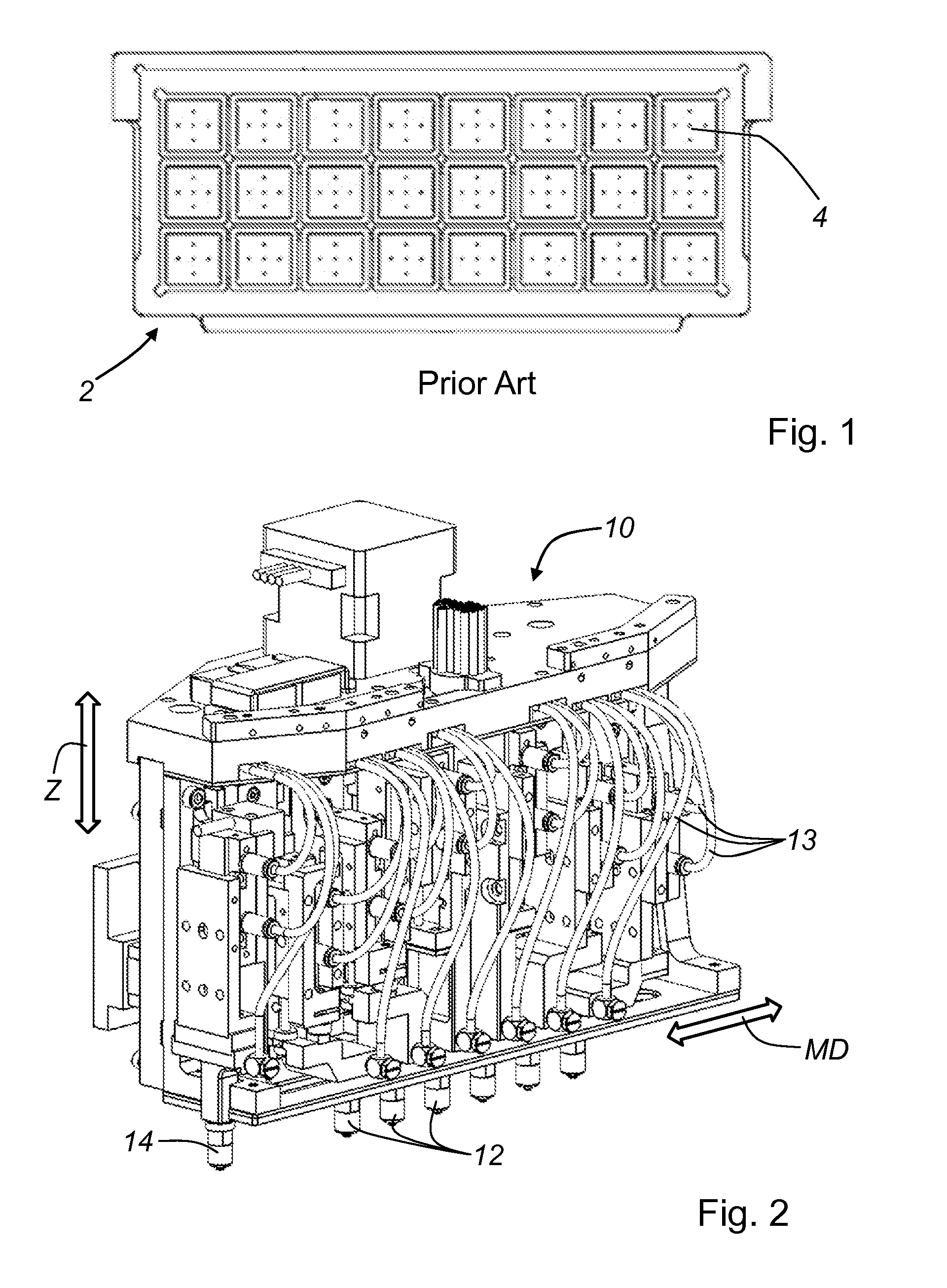
[0062]FIG. 1 shows one embodiment of a conventional JEDEC tray 2. The JEDEC tray 2 is a molded matrix carrier which is used during the manufacturing process of semiconductor devices to handle various components 6. The manufactured components (not shown) are placed in the individual cells 4 of the JEDEC tray 2. The placing of the components 6 in cells 4 is usually done by pick and place robots which have at least one pick and place head (see FIG. 2), The pick and place head typically comprises one or several grippers (or pickers) that can pick-up / remove an electronic component from a cell 4 of the JEDEC tray 2 and also place an electronic component into a cell 4 of the JEDEC tray 2.

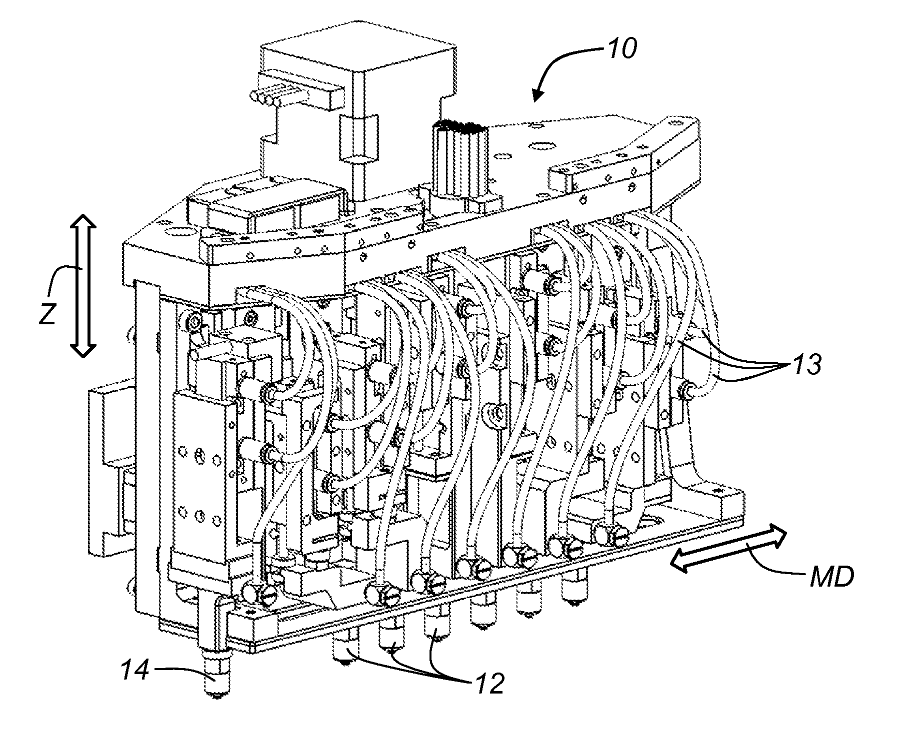
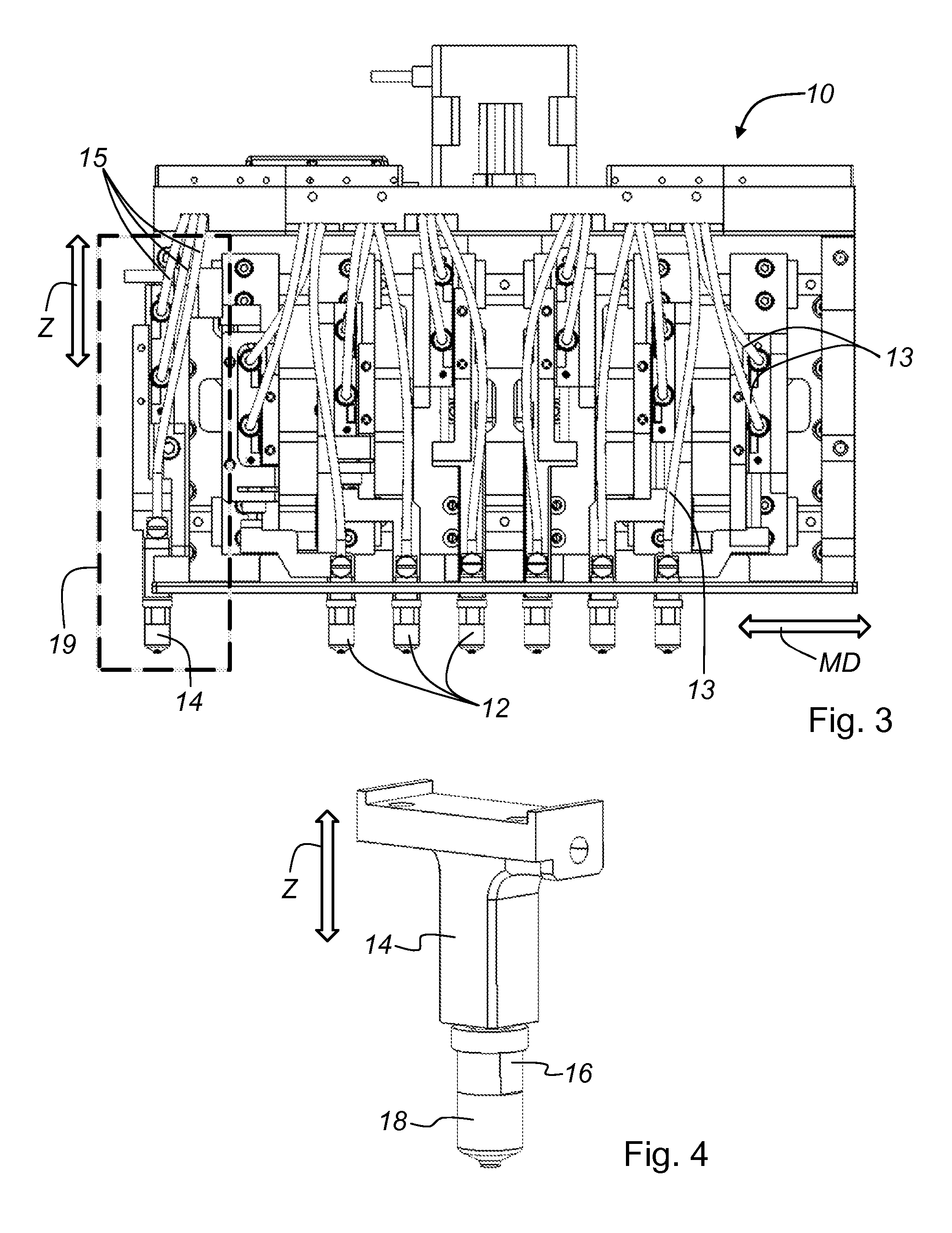
[0063]FIG. 2 and FIG. 3 are schematic views of a pick a...


PUM


Abstract

A pick and place device, a method and a computer program product for automatic pick- up-height adjustment. A first pneumatic system has a first and second controllable valves. The second controllable valve is connected with its input port to a vacuum source. An output port of the first controllable valve and an output port of the second controllable valve are connected to a common tube in fluid communication with at least one vacuum nozzle of the pick and place device. A second pneumatic system, with an inlet valve and an outlet valve are in fluid communication via a connecting tube. An open air exhaust and a flow controller are arranged in the connecting tube between the inlet valve and the outlet valve. A flow sensor detects the changes of the small air flow. The flow sensor is via a tube in fluid communication with the at least one vacuum nozzle.

Description

CROSS REFERENCE TO RELATED APPLICATIONS[0001]This application is filed under 35 U.S.C. §111(a) and §365(c) as a continuation of International Patent Application No. PCT / US2015 / 026478, filed Apr. 17, 2015, which application claims priority of U.S. Provisional Application No. 61 / 981,593, filed on Apr. 18, 2014, which applications are incorporated herein by reference in their entirety.FIELD OF THE INVENTION[0002]The present invention refers to a pick and place device with automatic pick-up-height adjustment.[0003]Furthermore, the present invention refers to a method to automatically adjust the pick-up-height of a pick and place device.[0004]Furthermore, the present invention refers to a computer program product disposed on a non-transitory computer readable medium to automatically adjust the pick-up-height of a pick and place device.BACKGROUND OF THE INVENTION[0005]Electronic components are often transported in (JEDEC) trays (a molded matrix carrier) during the manufacturing process. A...

Claims


Application Information

Patent Timeline
Patent Type & Authority Applications(United States)
IPC IPC(8): B25J9/16B25J15/06B25J13/08B25J5/02
CPCB25J9/1679B25J13/08B25J15/0625B25J5/02H05K13/0409
Inventor ACCOU, BRUNODE BLOCK, ERIK
Owner KLA TENCOR TECH CORP
Why Eureka
Try Eureka