
Rotating cleaning system

a rotating cleaning system and rotating technology, applied in the direction of cleaning process and equipment, cleaning using liquids, cleaning apparatus, etc., can solve the problems of limited flexibility and performance of dairy-type cip systems, inability to utilize the full spectrum of available cleaning parameters, and poor coverage, etc., to achieve the effect of achieving the target cleanliness level

Inactive Publication Date: 2010-07-29
MORK PROCESS
View PDF3 Cites 5 Cited by
  • Summary
  • Abstract
  • Description
  • Claims
  • Application Information

AI Technical Summary

Benefits of technology

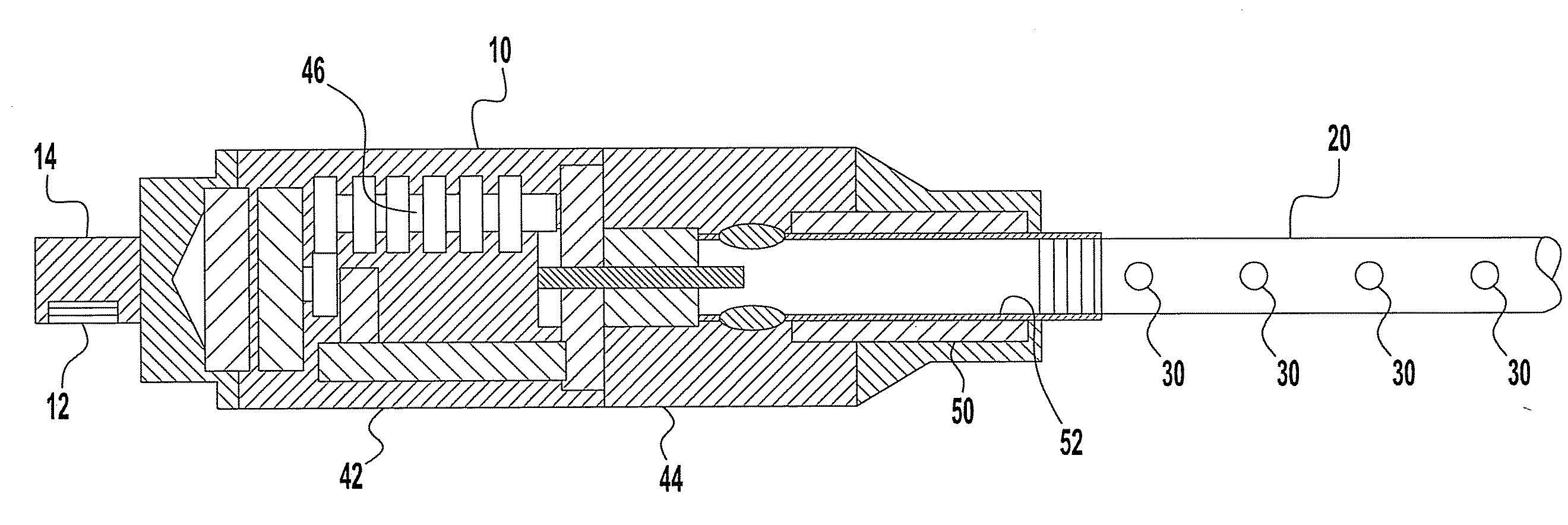
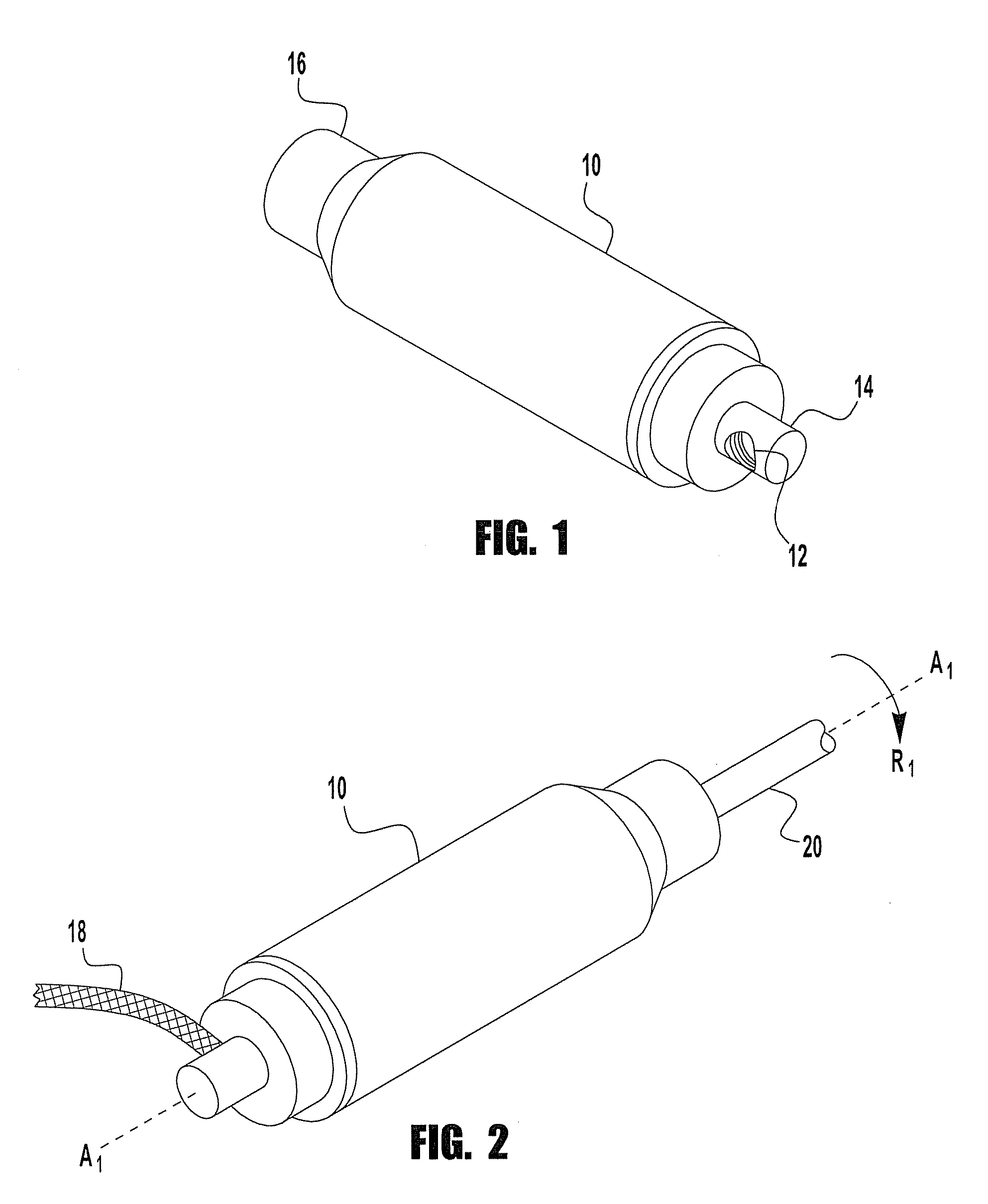
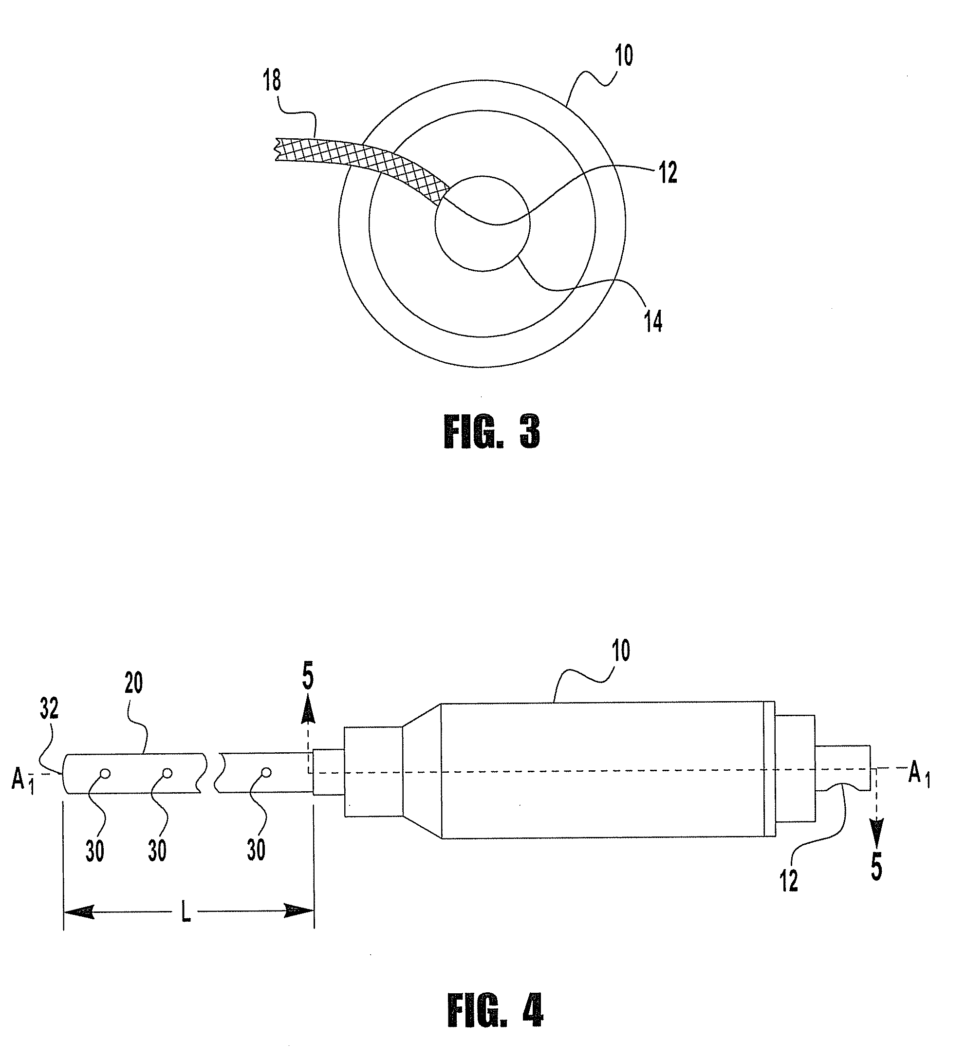
[0006]In an illustrated embodiment of the invention, a cleaning system for processing equipment includes a supply source of cleaning media, an apparatus including a main housing having a media inlet, media outlet, an internal media travel path defined between the media inlet and the media outlet, and a rotation generating mechanism. A rotational speed of the rotation generating mechanism is controllable by pressure flow of the media in the media travel path. A supply line connects the supply source and the media inlet. A rotatable lance is secured to the main body media outlet, and has at least one nozzle disposed between the media outlet and a distal end of the lance. The media is sprayed from the at least one nozzle in a rotational path. In an exemplary method, operational time, temperature, rotational speed as a function of pressure, and media type are controlled to reach a target cleanliness level.

Problems solved by technology

Cleaning media are applied with static spray balls that have a very poor coverage, and impingement, and cleaning is based upon long cleaning times with high volumes of water and chemicals.
Such “dairy-type” CIP systems are limited in flexibility and performance, and cannot utilize the full spectrum of available cleaning parameters, such as time, action (meaning pressure and flow), chemistry, temperature, etc., to enhance cleaning results.
As a result, they continue to re-invent “dairy-type” CIP systems, using high volume and low pressure, that consume more resources and produce poorer quality cleaning results than could otherwise be achieved.

Method used


Image

  • Rotating cleaning system
  • Rotating cleaning system
  • Rotating cleaning system

Examples


Embodiment Construction

[0019]The Detailed Description of the Invention merely describes preferred embodiments of the invention and is not intended to limit the scope of the specification or claims in any way. Indeed, the invention as described by the claims is broader than an unlimited by the preferred embodiments, and the terms in the claims have their full ordinary meaning.

[0020]The present invention relates to a system for cleaning food processing equipment. In one discussed embodiment, the system is used in the food industry to clean production equipment at the conclusion of production runs, or in between production cycles. An exemplary cleaning system includes a media driven and media lubricated rotating apparatus. The media selected acts as a cleaning fluid and is selected for contact with food.

[0021]The inventive cleaning system utilizes and combines the full spectrum of cleaning parameters, including, e.g., time, action, chemistry and temperature, to ensure a successful, robust and validated clean...


PUM


Abstract

A cleaning system for food processing equipment is disclosed. An exemplary system includes a supply source of cleaning media, an apparatus including a main housing having a media inlet, media outlet, an internal media travel path defined between the media inlet and the media outlet, and a rotation generating mechanism, wherein rotational speed of the rotation generating mechanism is controllable by pressure flow of the media in the media travel path. A supply line connects the supply source and the media inlet. A rotatable lance secured to the main body media outlet, and has at least one nozzle disposed between the media outlet and a distal end of the lance. The media is sprayed from the at least one nozzle in a rotational path. A method of use is also disclosed. In an exemplary method, operational time, temperature, pressure, rotational speed and media type are controlled to reach target cleanliness levels.

Description

FIELD OF THE INVENTION[0001]The present invention relates to a system for in-line cleaning of food processing equipment during production downtime.BACKGROUND OF THE INVENTION[0002]Manufacturers in many industries, such as food and pharmaceutical processing, need to deal with variations in production flows, including rapid change over from one product to another, while maintaining a high production through-put and insuring that the integrity and quality of the manufactured products meet good manufacturing practice (“GMP”) standards. In order to maintain product integrity and quality, manufacturing equipment must be properly cleaned, especially between product runs.[0003]Historically, food and pharmaceutical manufacturers have relied on traditional clean-in-place (“CIP”) methods and equipment that follow well-known guidelines to utilize technology, designs and philosophies dating back to the dairy industry of the 1950's. Such CIP systems are constructed around multiple vessels (each v...

Claims


Application Information

Patent Timeline
Patent Type & Authority Applications(United States)
IPC IPC(8): B08B3/02B08B9/093
CPCB05B1/202B05B1/267B05B3/0422B05B13/06B08B3/02B08B9/0936
Inventor MADSEN, OLE T.
Owner MORK PROCESS
Learn More