Air management system and method for chemical containment and contamination reduction in a semiconductor manufacturing facility

a technology for chemical containment and contamination reduction, which is applied in ventilation systems, heating types, separation processes, etc., can solve the problems of air turbulence in the vicinity, increased difficulty in ccv, and occasional spillage of fumes into the process and operator environment, so as to prevent deleterious condensation of chemical fumes and reduce the escape of chemical fumes

Inactive Publication Date: 2002-09-26
ADVANCED TECH MATERIALS INC
View PDF0 Cites 1 Cited by
  • Summary
  • Abstract
  • Description
  • Claims
  • Application Information

AI Technical Summary

Benefits of technology

[0029] In a specific aspect, the air manager of such type, installed in an open architecture wet bench facility and with the air source member incorporating or arranged for connection to a high purity air supply, may be employed to provide a level of cleanliness approaching that routinely achieved by far more expensive mini-environment wet bench facilities.
[0039] at least one scroll lid assembly as described hereinabove, positioned above the chemical tank, for reducing escape of chemical fumes from said chemical tank into a surrounding environment.
[0040] Such chemical tank assembly may also incorporate an air manager as described hereinabove to prevent deleterious condensation of chemical fumes underneath the thin film member of the scroll lid assembly, wherein the air manager may be placed between the scroll lid assembly and the chemical tank below it.
[0046] at least one environmental management system, selected from the group consisting of air managers and scroll lid assemblies, positioned to substantially prevent escape of the chemical fuimes from the vicinity of the wet bench.

Problems solved by technology

On the other hand, many semiconductor manufacturing process steps involve the use of chemicals that are toxic or otherwise hazardous to humans, which also necessitates use of localized exhaust equipment to contain, remove, or otherwise abate fumes from such chemicals.
When such air stream is pulled further down to beneath the deck level, semiconductor processing equipment, most notably chemical tanks, obstruct flow path for such air stream and induce air turbulence in their vicinity.
Because of these factors, conventional exhaust systems exhibit marginal fume capture capability, and many fail to consistently control contamination and hazardous fuimes under the deck, resulting in occasional fumes spills into the process and operator environment.
As wafer sizes used in the semiconductor industry grow to 300 mm or more and require larger deck openings, however, CCV becomes more difficult to achieve, and facility exhaust capacity is stretched beyond its limits.
Conventional push-pull systems will not be able to produce enough combined force to achieve capture of hazardous fumes in large size wafer facilities now under design and construction.
Additionally, the exhaust systems in many 200-millimeter (mm)-facilities in current use are unable to achieve CCV because of a disparity in the exhaust capacity, deck opening sizes, and laminar push.
Consequently, fume spill incidents occur in many wafer fabs, resulting in yield loss, excessive rework, process disruption, environmental and regulatory noncompliance, injury, and litigation.
A serious problem associated with such immersion wet cleaning process is that the liquid chemicals contained by the chemical tanks release hazardous fumes at their surfaces.
Such fumes tend to migrate to the environment surrounding the tanks and pose environmental hazards or cause worker injuries.
High capacity exhaust systems are expensive, energy-consuming, and difficult to install and maintain.
Moreover, pressure fluctuations in the exhaust air stream or in the semiconductor processing system overall still cause deleterious turbulence and loss of fume control at certain localities in the system, resulting in formation of "plumes" of hazardous vapors.
Such lids significantly reduce the flexibility of wet processing systems as well as the wafer throughput.
The opening and closing of such lids still results in local turbulence.
Accordingly, such lids cannot completely eliminate escape of chemical fuimes from the chemical tank.
Moreover, currently available safety lids are mechanically complex, expensive, and difficult to maintain.
Further, hazardous chemical vapors tend to condense on the bottoms of the safety lids, which may result in more severe worker injuries or potential environmental problems.

Method used


Image

  • Air management system and method for chemical containment and contamination reduction in a semiconductor manufacturing facility
  • Air management system and method for chemical containment and contamination reduction in a semiconductor manufacturing facility
  • Air management system and method for chemical containment and contamination reduction in a semiconductor manufacturing facility

Examples


example 1

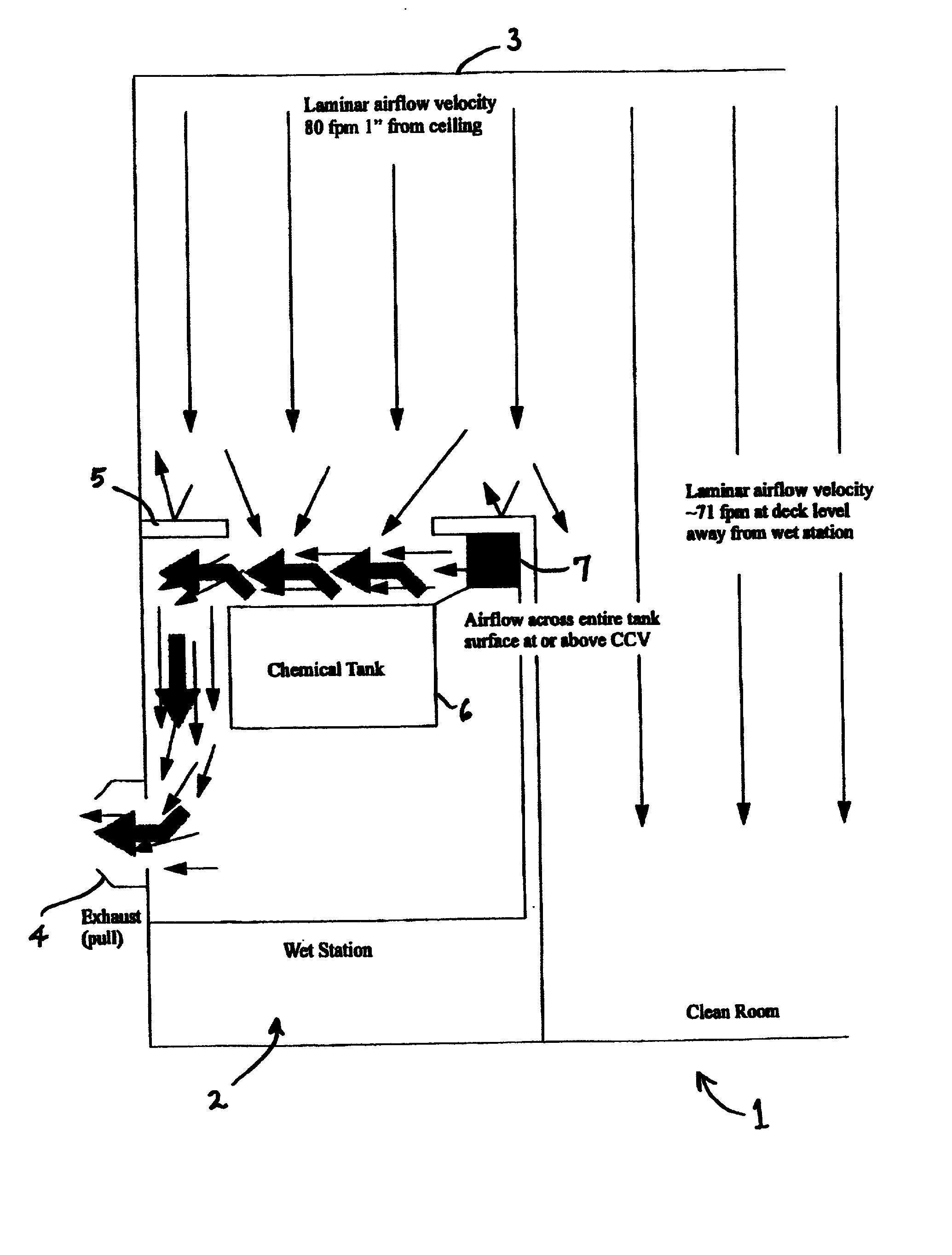
[0118] The air management system of the invention was evaluated in a semiconductor manufacturing facility wet system including a deck that was 128.5 inches in length, overlying a series of process tanks, comprising in sequence a chuck wash tank, a U CLEAN tank, two rinse tanks, two HF tanks, and two rinse tanks.

[0119] The U CLEAN tank and one of the HF tanks were studied by velocity profile and fog visualization tests. The deck openings for these tanks were each 11 inches by 15.5 inches. The U CLEAN tank was 16.5 inches wide by 26 inches long, and the HF tank had the same dimensions. Each tank was 11.75 inches tall, and the spacing distance between the upper end of the tank walls and the deck was 6.5 inches. The exhaust box for each tank had an exhaust duct opening 8 inches in diameter.

[0120] Measurements were taken at the deck opening above the process tank in each case. The deck opening above each process tank was divided into a 4.times.3 grid, and measurements were taken in the c...


PUM

PropertyMeasurementUnit
velocityaaaaaaaaaa
sizesaaaaaaaaaa
velocityaaaaaaaaaa

Abstract

An air manager and / or chemical containment apparatus, for environmental control of fumes from wet bench units of semiconductor manufacturing facilities. The air manager system is suitable for installation in an open architecture wet bench or an enclosed mini-environment wet bench, and includes an air source and an air exhaust arranged for flowing air across an open chemical tank, to entrain fumes from chemical in the tank that otherwise may migrate from the immediate vicinity of the tank, and transport such fumes to the exhaust with the air flowed from the air source to the exhaust. The chemical containment apparatus includes: (1) a thin film member including at least one solid portion and at least one cut-out portion; (2) a first scroll member positioned at one side of the thin film member for rotatorily moving the thin film member; (3) a motive driver operatively connected to the first scroll member for rotating the first scroll member; and (4) optionally, a second scroll member positioned at the other side of said thin film member for rotatorily receiving said thin film in synchrony with movement of the first scroll member.

Description

FIELD OF THE INVENTION[0001] The present invention generally relates to environmental control in semiconductor manufacturing operations, including management of airflow in controlled environments and containment and capture of hazardous fume species. More particularly, the present invention relates to improved chemical containment and contamination reduction apparatuses, systems, and processes in semiconductor manufacturing facilities. In a specific aspect, the invention relates to a chemical containment apparatus for capturing and reducing hazardous chemical fumes released by chemical tanks used in a semiconductor wet processing system.DESCRIPTION OF THE RELATED ART[0002] Semiconductor manufacturing must be performed in a particle-free environment, due to the fact that submicron size dimensions characterize the structural elements of the electronic circuitry, and that such circuitry can be rendered inoperative by the presence of even a single particle of dust. Semiconductor manufac...

Claims


Application Information

Patent Timeline
Patent Type & Authority Applications(United States)
IPC IPC(8): B01D53/74F24F7/06F24F7/003H01L21/00H01L21/306
CPCB01D53/74F24F3/161F24F2007/001H01L21/67017H01L21/6715Y10S55/18Y10S55/29F24F3/167F24F7/003
Inventor OLANDER, W. KARLWALKER, BRUCE G.
Owner ADVANCED TECH MATERIALS INC
Why Eureka
Try Eureka