

Microwave oven
a microwave oven and microwave technology, applied in the field of microwave ovens, can solve the problems of inconvenient placing of food in the cooking chamber, inconvenient placing of articles on both sides of the microwave oven, and inconvenient use of the microwave oven of the related art, and achieve the effects of convenient loading and unloading, large room, and efficient us
- Summary
- Abstract
- Description
- Claims
- Application Information
AI Technical Summary
Benefits of technology
Problems solved by technology
Method used
Image

Examples
first embodiment
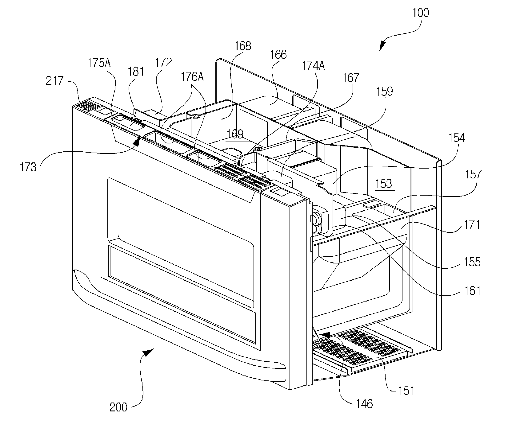
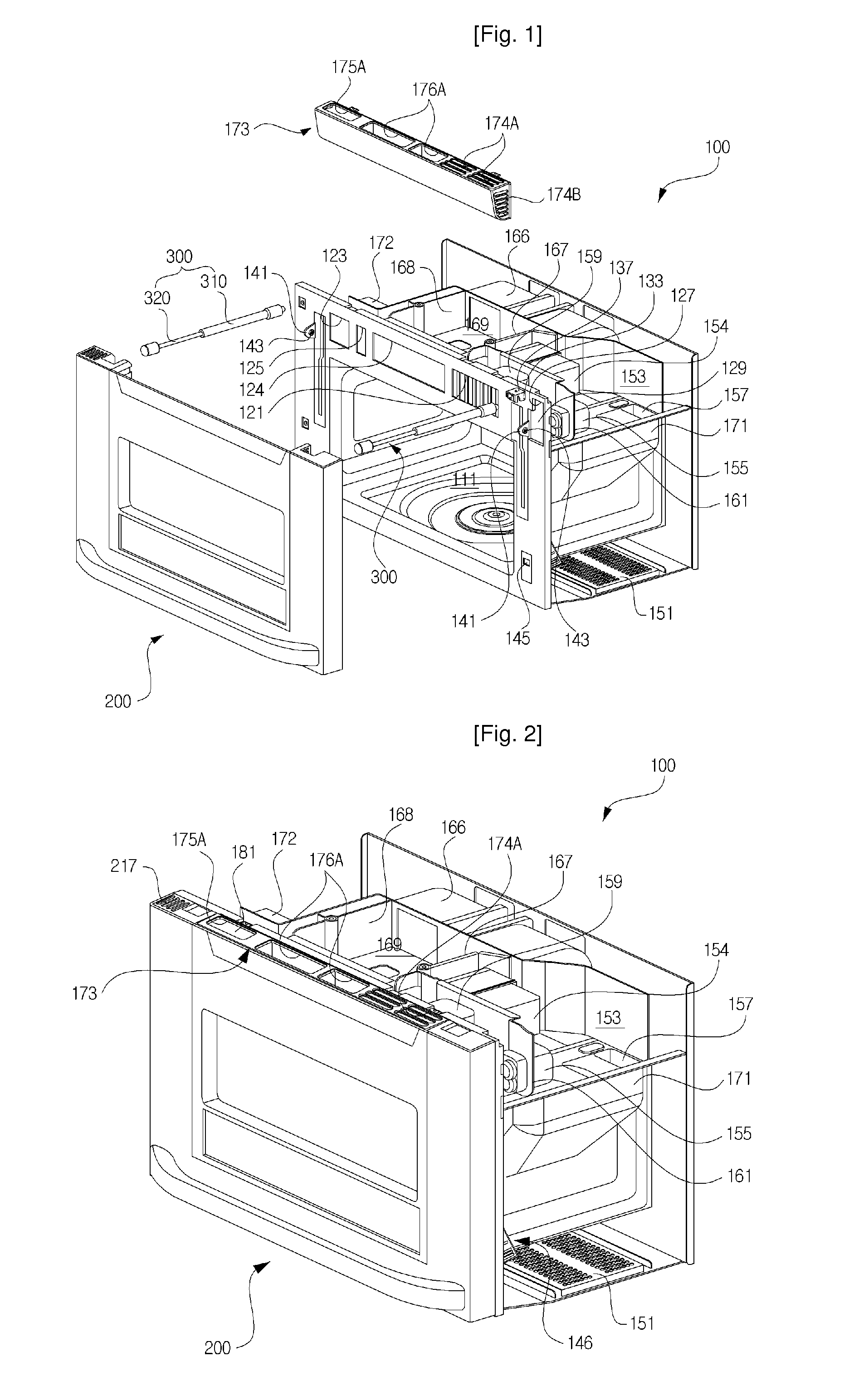
[0033]A microwave oven will now be described in detail with reference to the accompanying drawings according to a
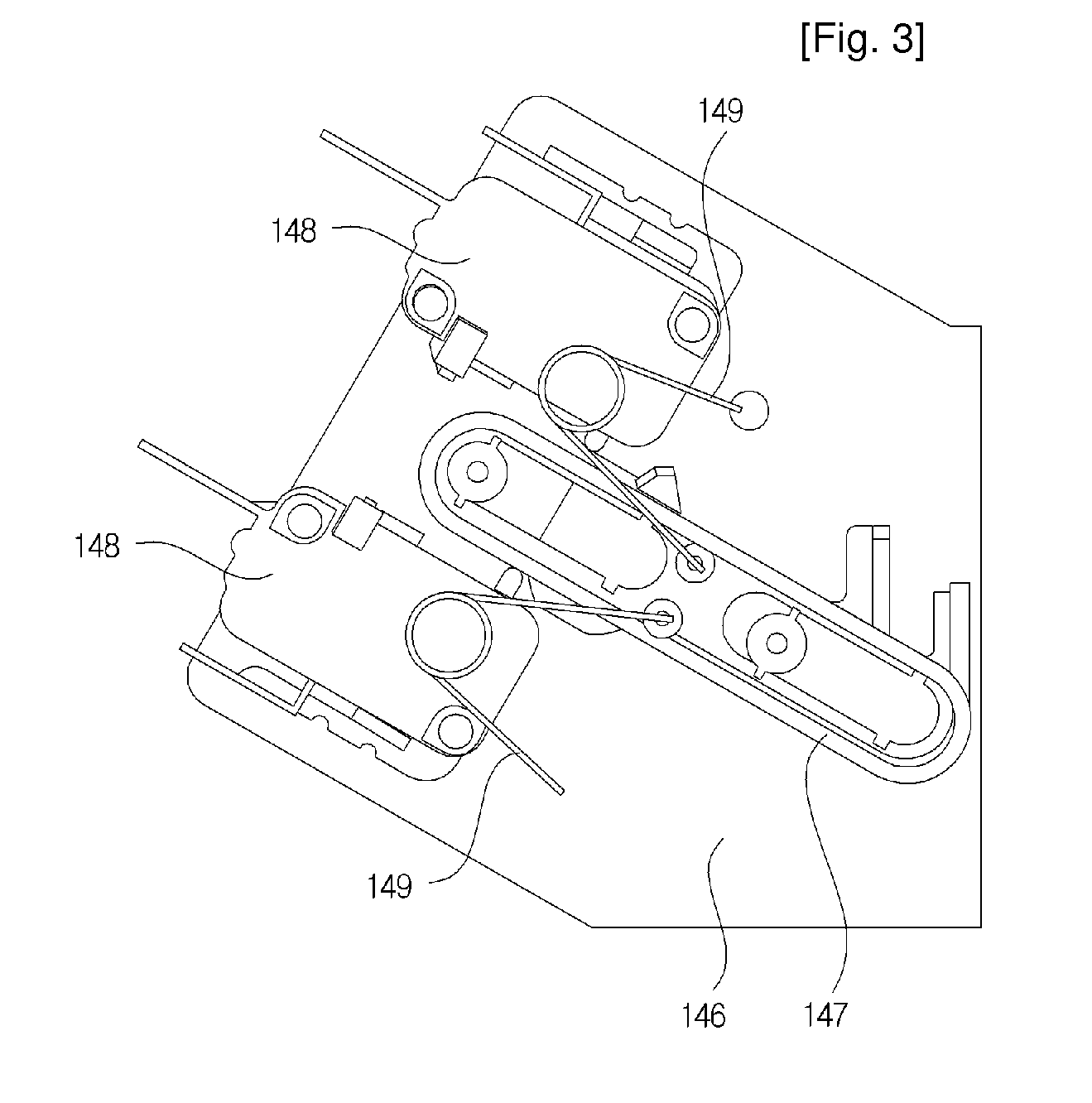
[0034]FIG. 1 is an exploded perspective view illustrating a microwave oven according to a first embodiment, and FIG. 2 is a perspective view illustrating an assembled state of the microwave oven according to the first embodiment. FIG. 3 is a vertical sectional view illustrating a latch board according to the first embodiment, and FIG. 4 is a perspective view illustrating a door support bracket according to the first embodiment. FIG. 5 is a perspective view illustrating an air barrier according to the first embodiment, and FIG. 6 is a perspective view illustrating a vent grill and a lead wire cap according to the first embodiment. FIG. 7 is a vertical sectional view illustrating an assembled state of the vent grill and the lead wire cap according to the first embodiment, and FIG. 8 is an exploded perspective view illustrating a door according to the first embodiment. FIG. ...
fourth embodiment
[0144]A microwave oven will now be described in detail with reference to the accompanying drawings according to a
[0145]FIG. 23 is a perspective view illustrating a cam hinge of a microwave oven according to a fourth embodiment.
[0146]In the current embodiment, a cooking chamber (not shown) disposed in a cavity assembly (not shown) is closed and opened using a door (not shown), and a pair of cam hinges 600 (one shown in FIG. 23) is used to attach the door to the cavity assembly in a manner such that a lower end of the door can be rotated about an upper end of the door.
[0147]The cam hinges 600 apply a torque to the door in a direction for opening the door or closing the door according to the angular position of the door. In other words, the cam hinges 600 apply a torque to the door in different directions based on a reference angular position of the door. For example, when the door is positioned above the reference regular position, the cam hinges 600 apply a torque to the door in a pr...
PUM
 Abstract
Description
Claims
Application Information