Decompression device for an aircraft

Active Publication Date: 2010-07-29
AIRBUS OPERATIONS GMBH
View PDF12 Cites 27 Cited by
  • Summary
  • Abstract
  • Description
  • Claims
  • Application Information

AI Technical Summary

Benefits of technology

[0006]The invention may provide a more simply designed device for quick pressure com

Problems solved by technology

Furthermore, the simpler design saves weight.
Furthermore, this creates a barrier for objec

Method used


Image

  • Decompression device for an aircraft
  • Decompression device for an aircraft
  • Decompression device for an aircraft

Examples


Example

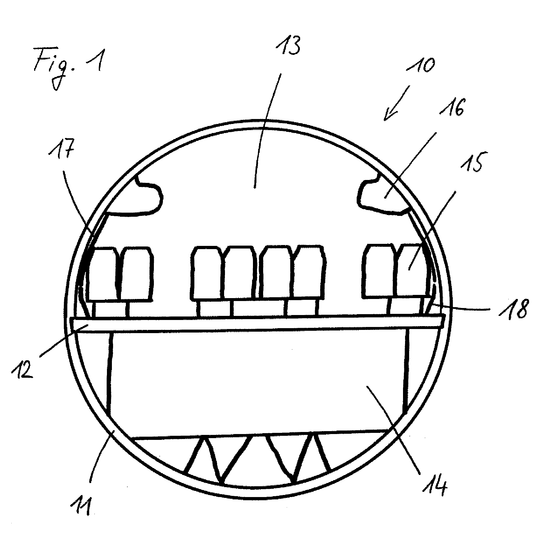
[0022]FIG. 1 shows a cross section of an aircraft fuselage. This aircraft fuselage 10 is delimited by the exterior skin 11 of the fuselage, within which various regions that are separate of each other are formed. For example, a passenger region 13 is separated from a cargo region 14 by means of a cabin floor 12. In the passenger region 13, passenger seats 15 with hatracks 16 arranged overhead are provided. On the inside of the exterior skin 11 of the fuselage the passenger region 13 is lined with lateral cover panels 17 and, between the outer passenger seats and the exterior skin 11 of the fuselage in the region of the foot space, with cover panels 18, also referred to as dado panels.

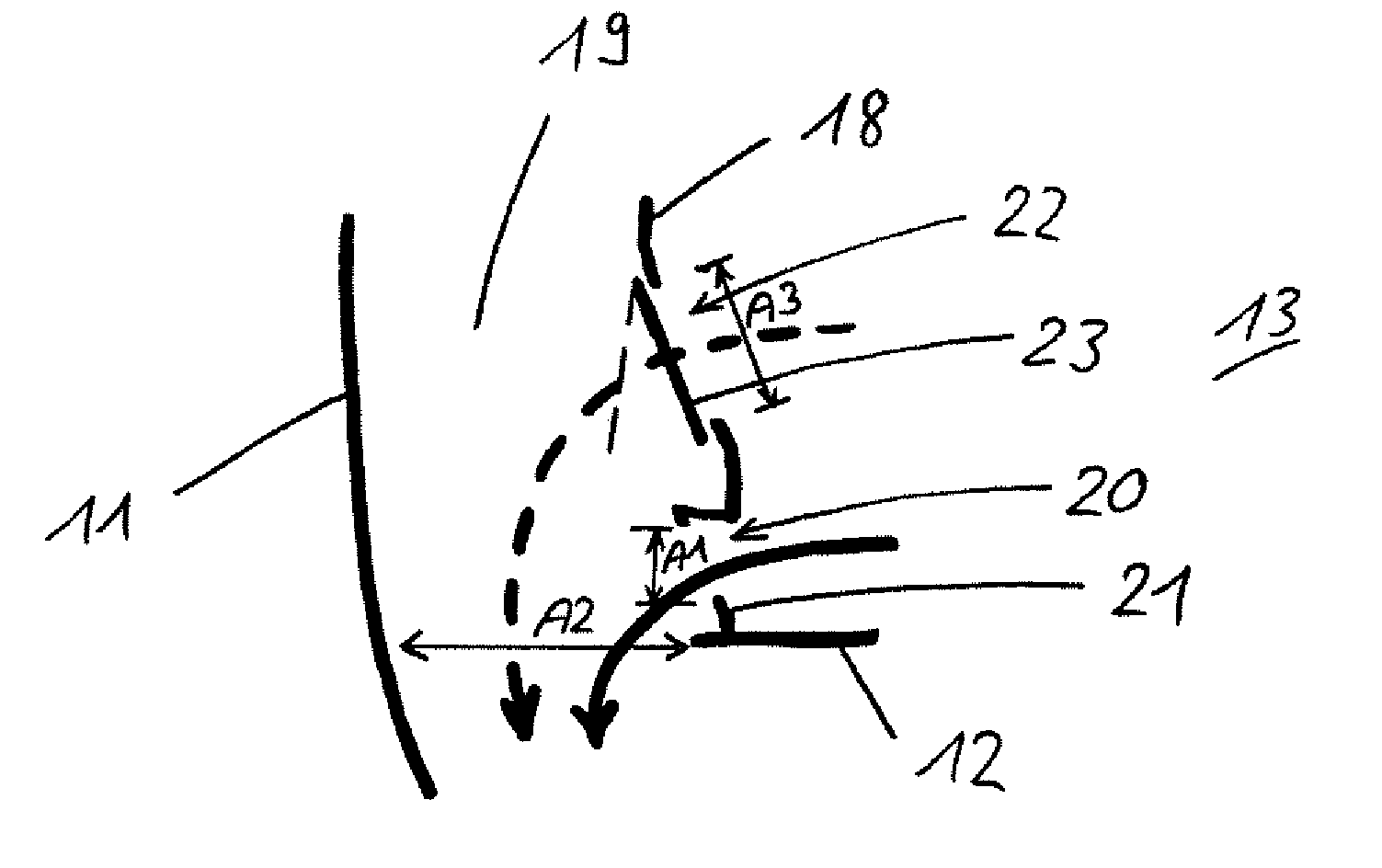
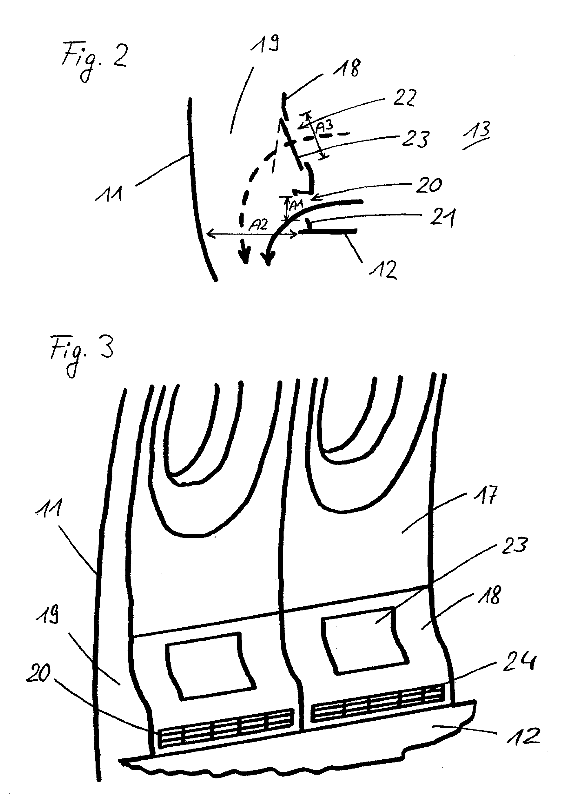
[0023]FIG. 2 diagrammatically shows a cover panel 18 with the decompression device according to the invention. As apparent from the illustration, a flow passage 19 is formed between the exterior skin 11 of the fuselage and the cover panel 18, which flow passage 19 makes it possible for air to pass betwe...


PUM


Abstract

The invention relates to a cover panel for an aircraft, comprising a decompression opening that can be closed by a decompression flap that comprises a membrane, and a ventilation opening that is provided separately in the cover panel and that is permanently open. Furthermore, the invention relates to an aircraft fuselage comprising such a cover panel.

Description

CROSS-REFERENCE TO RELATED APPLICATIONS[0001]This application claims the benefit of the filing date of U.S. Provisional Patent Application No. 61 / 147,799 filed Jan. 28, 2009, the entire disclosure of which application is hereby incorporated herein by reference.BACKGROUND OF THE INVENTION[0002]The invention relates to a cover panel for an aircraft, comprising a decompression opening.[0003]The fuselage of a normal passenger aircraft is divided into several regions, among others a passenger region and a cargo region. During cruise flights, the aircraft is surrounded by cold environmental conditions of low air pressure, which requires air conditioning and pressurisation of the aircraft fuselage. For this purpose, bleed air from the engines is normally introduced into the passenger cabin, which bleed air, when it has passed through the passenger region, can escape from the passenger region through ventilation openings that have been placed in the cover panels such that they are positione...

Claims


Application Information

Patent Timeline
IPC IPC(8): B64C1/14B64D13/00
CPCB64C2001/009B64C1/18
Inventor VOSS, JENSHORST, MARKUSROTH, INGO
Owner AIRBUS OPERATIONS GMBH
Why Eureka
Try Eureka