Device and method for obtaining a three-dimensional topography

Inactive Publication Date: 2010-11-25
ROBERT BOSCH GMBH
View PDF7 Cites 9 Cited by
  • Summary
  • Abstract
  • Description
  • Claims
  • Application Information

AI Technical Summary

Benefits of technology

[0005]The device according to the present invention for obtaining a three-dimensional topography of a measured object has the advantage over the related art that a simply designed and cost-effective approach is provided via which even complex three-dimensional topographies, in particular on round components, may be detected. According to the present invention, a three-dimensional topography is obtained based on the use of structured light. According to the present invention a

Problems solved by technology

However, in this known method the equipment design is very bulky and complicated.
The known methods also have the disadvantage that for unfavorab

Method used


Image

  • Device and method for obtaining a three-dimensional topography
  • Device and method for obtaining a three-dimensional topography

Examples


Example

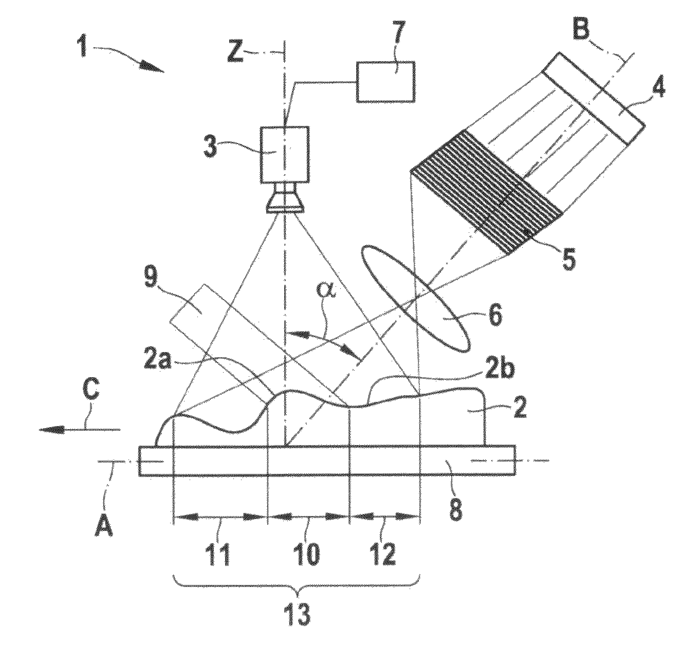
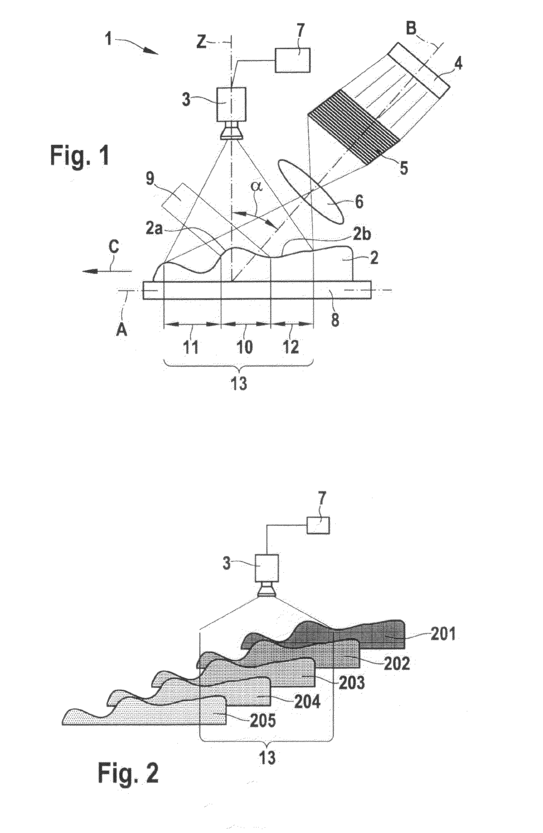
[0017]A device 1 and a method for obtaining a three-dimensional topography of a measured object 2 are described in greater detail below with reference to FIGS. 1 and 2.

[0018]As is apparent in FIG. 1, device 1 for obtaining a three-dimensional topography of a measured object 2 includes a 2D camera 3, an illumination system having a light source 4, a grid 5, and a lens 6; a computing unit 7, and a movement device 8. Measured object 2 is situated on movement device 8. Movement device 8 is able to move in the direction of an axis A, for example to the left in FIG. 1. As is apparent in FIG. 1, a center axis B of the illumination system is situated at an angle α of approximately 45° with respect to a recording direction Z of 2D camera 3. This configuration of the illumination system at an angle α with respect to recording direction Z results in a focal plane 9, which is schematically indicated in FIG. 1. This results in a focused area 10 as well as a first unfocused area 11 and a second u...


PUM


Abstract

In a device for obtaining a three-dimensional topography of a measured object, a center axis of an illumination system is situated at an angle with respect to a recording direction of a 2D camera, and the illumination system generates a focal plane on a predetermined area of the measured object, the predetermined area being smaller than a recording area of the 2D camera. The measured object is movable relative to the 2D camera and relative to the illumination system with the aid the movement device. The 2D camera records multiple images of the measured object from various positions which are occupied due to the movement of the movement device.

Description

BACKGROUND OF THE INVENTION[0001]1. Field of the Invention[0002]The present invention relates to a device and a method for obtaining a three-dimensional topography of a measured object, using a two-dimensional (2D) camera.[0003]2. Description of Related Art[0004]Depth-scanning fringe projection or other three-dimensional methods are used in the related art for obtaining three-dimensional topographies of measured objects. An optical method for obtaining a three-dimensional (3D) point cloud is known, for example, from published German patent application document DE 100 56 073 A1, in which a 3D camera is used which, together with an illumination system, is moved in a direction perpendicular to the measured object and records a series of images. However, in this known method the equipment design is very bulky and complicated. The known methods also have the disadvantage that for unfavorable surface conditions, for example for round components such as screws or the like, it is difficult ...

Claims


Application Information

Patent Timeline
IPC IPC(8): G06K9/36
CPCG01B11/2522
Inventor SEIFFERT, THOMAS
Owner ROBERT BOSCH GMBH
Why Eureka
Try Eureka