Press for a machine for producing a fibrous material web

Active Publication Date: 2018-12-27
VOITH PATENT GMBH
View PDF4 Cites 0 Cited by
  • Summary
  • Abstract
  • Description
  • Claims
  • Application Information

AI Technical Summary

Benefits of technology

[0021]According to one embodiment of the invention, the suction guide roll has no rotary drive and no transmission. A manifold of the suction guide roll can thus be designed more simply. Alternatively, hereto, the suction guide roll can however also be equipped with a rotary drive and possibly

Problems solved by technology

Suction felt guide rolls are used in particular at web speeds in excess of 1100 m/min to 1200 m/min because in this case the previously described web separation by means of a cost-effective suction box is no longer possible.
Suction felt guide rolls offer the advantage of a very reliable web separation up to high speeds, however they are very expensive in regard to investment costs, spare parts and maintenance.
A conventional suction felt guide roll usually has two or multiple zones, which is why a relatively expensive manifold becomes necessary for suction.
A conventional suction felt guide roll moreover requires a rotary drive since it is subject to friction and uses up drive power in the felt loop.
The drive moreover allows the felt tension to drastically drop directly after the press nip, which could lead to malfunctions in web travel.
Alternatively, the rotary drive on the drive side can be designed centrically, in which case however the suction needs to be relocated to the operator side of the press, which is expensive.
Despite the provi

Method used


Image

  • Press for a machine for producing a fibrous material web
  • Press for a machine for producing a fibrous material web

Examples


first embodiment

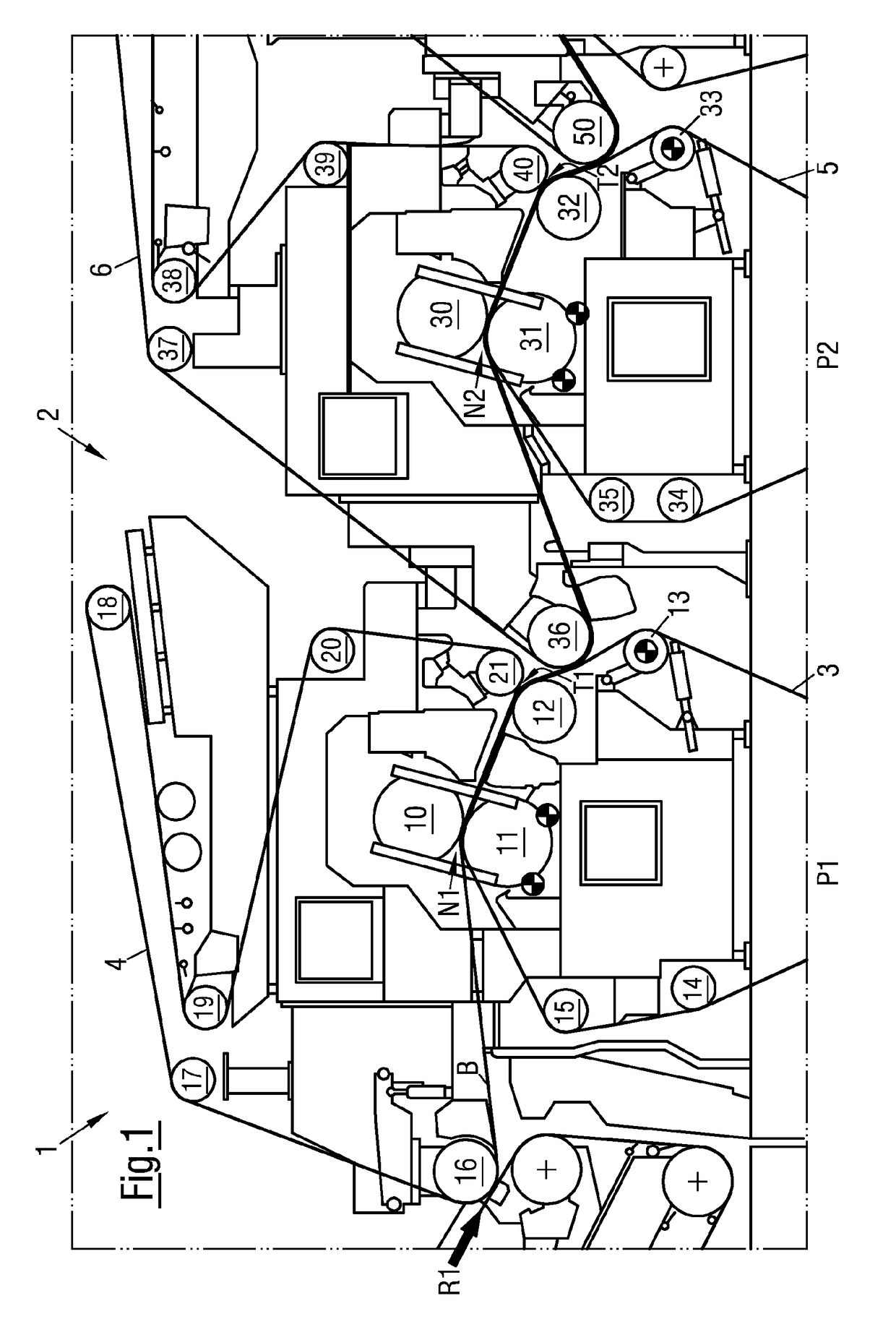
[0030]Referring to the drawings and more particularly to FIG. 1 there is shown a press 2 of a machine 1 (not shown in its entirety) to produce a fibrous web B, is described with reference to FIG. 1. In the present embodiment of the invention, press 2 is a so-called tandem press with two consecutive press stages P1, P2.

[0031]Machine 1 in the present embodiment of the invention is a paper machine for the production of a paper, cardboard or pulp web in the form of a fibrous web B. Fibrous web B can be a packaging paper web or a cardboard web and is run in press 2 at a web speed of ≥1100 m / min, preferably ≥1150 m / min and even more preferably ≥1200 m / min in a direction of web travel R1.

[0032]In its first press stage P1, press 2 has a first press nip N1 which is formed between press roll 10 and a counter press roll 11 of first press stage P1 in order to guide fibrous web B through, in a dewatering manner. In other words, first press stage P1 of press 2 is equipped with press roll 10 and ...

second embodiment

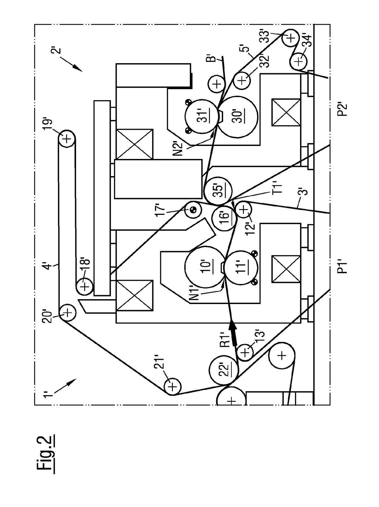
[0043]According to another embodiment of the invention a press 2′ in a machine 1′ (not shown in its entirety) for the production of a fibrous web B′ is described below with reference to FIG. 2. In the invention, press 2′ is also designed as a tandem press with two consecutive press stages P1′, P2′.

[0044]Machine 1′ in the present embodiment of the invention is a paper machine for the production of a paper, cardboard or pulp web in the form of a fibrous web B′. Fibrous web B′ is preferably a packaging paper web or a cardboard web and is run in press 2′ at a web speed of ≥1100 m / min, preferably ≥1150 m / min and even more preferably ≥1200 m / min in a direction of web travel R1′.

[0045]In its first press stage P1′, press 2′ has a first press nip N1′ which is formed between press roll 10′ and a counter press roll 11′ of first press stage P1′ in order to guide fibrous web B′ through, in a dewatering manner. In other words, first press stage P1′ of press 2′ is equipped with press roll 10′ and ...


PUM


Abstract

The invention relates to a press for a machine for producing a fibrous material web, including at least one press nip formed between a press roller and a counter press roller of the press for guiding through the fibrous material web in a dehydrating manner, and two band shaped covers, which are each guided by multiple guide rollers in continuous circulation, so as to run together through the press nip, so that the fibrous material web is guided through sandwiched between said covers, and then separated again at a separation point, in order to continue guiding the fibrous material web on the one cover and separate it from the other cover. One guide roller of the guide rollers arranged at the separation point is a suctioned guide roller of the one cover, to hold the fibrous material web on the one cover at the separation position.

Description

CROSS REFERENCE TO RELATED APPLICATIONS[0001]This is a continuation of PCT application No. PCT / EP2016 / 080968, entitled “PRESS FOR A MACHINE FOR PRODUCING A FIBROUS MATERIAL WEB”, filed Dec. 14, 2016, which is incorporated herein by reference.BACKGROUND OF THE INVENTION1. Field of the Invention[0002]The invention relates to a press for a machine for producing a fibrous material web, in particular a paper, cardboard, or pulp web.2. Description of the Related Art[0003]A press for a machine for producing a fibrous material web is known for example from DE 10 2011 082 161 A1. The press described therein includes at least one press nip and two ribbon-like fabrics in the embodiment of a bottom felt and a top felt. The at least one press nip is formed between a press roll and a counter press roll of the press in order to guide the fibrous web through, in a dewatering manner. The bottom felt and the top felt respectively are guided by a multitude of guide rolls, so that they are brought toge...

Claims


Application Information

Patent Timeline
IPC IPC(8): D21F3/04D21F7/02D21F3/10
CPCD21F3/045D21F7/02D21F3/10D21F1/40D21F3/04
Inventor GRONYCH, DANIELRUHL, THOMAS
Owner VOITH PATENT GMBH
Why Eureka
Try Eureka