Arrangement of an electrical machine

Active Publication Date: 2012-07-31
AUDI AG
View PDF9 Cites 0 Cited by
  • Summary
  • Abstract
  • Description
  • Claims
  • Application Information

AI Technical Summary

Benefits of technology

[0005]It is proposed according to the invention that there is an intermediate shaft between the power delivery shaft of the internal combustion engine and the rotor of the electrical machine and that within the axial distance which has been formed in this way, the output shaft of the differential is positioned for driving a wheel of the motor vehicle, which output shaft runs transversely to the drive axis of rotation. This arrangement makes it possible, for example in front-wheel drive of the mo

Problems solved by technology

Since the electrical machine is connected downstream from the internal combustion engine in an arrangement in a motor vehicle, in conjunction with a likewise necess

Method used


Image

  • Arrangement of an electrical machine
  • Arrangement of an electrical machine
  • Arrangement of an electrical machine

Examples


Embodiment Construction

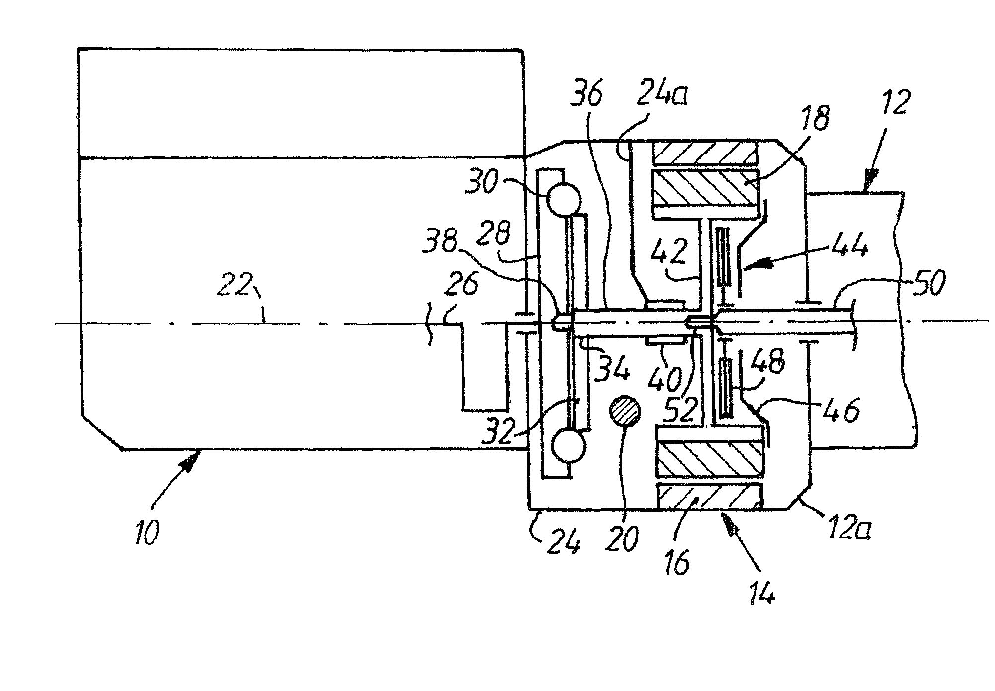
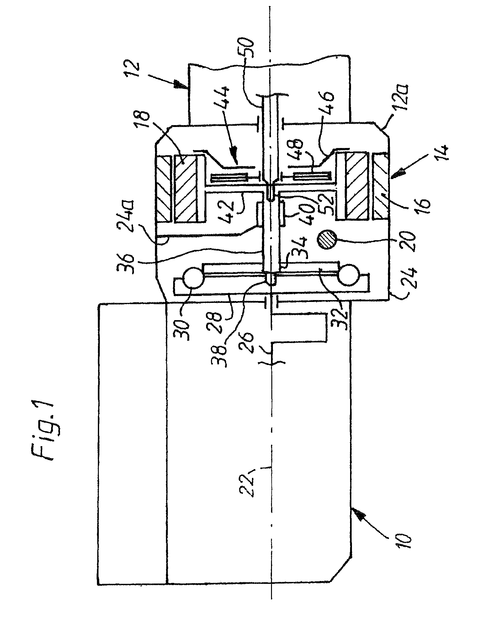
[0021]The drive arrangement shown as a block diagram in FIG. 1 has an internal combustion engine 10, a downstream, only partially outlined speed-change transmission 12, and as the electrical machine a starter-generator device 14 with a ring-shaped stator 16 and a ring-shaped rotor 18. The indicated components are of conventional design for motor vehicles to the extent not described; thus the transmission 12 can be a manual transmission or an automatic transmission, the device 14 can be any type of electrical machine, for example an electrical asynchronous three-phase machine by means of which the internal combustion engine 10 is started and the vehicle can be driven in hybrid drive.

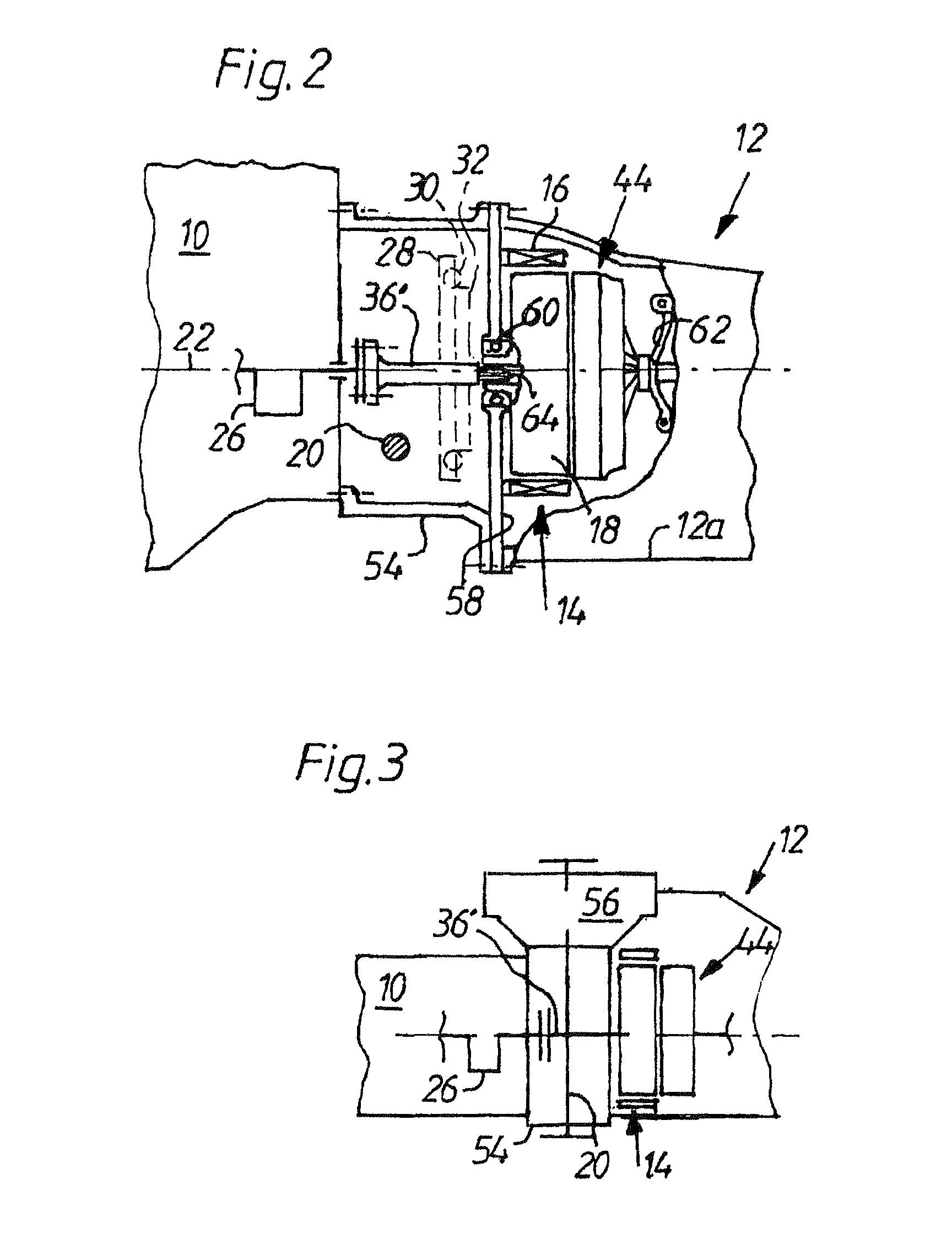
[0022]A differential is laterally mounted on to the transmission 12 in a manner which is not visible in FIG. 1; the output shaft 20 of the differential underneath the axis of rotation 22 of the drive arrangement 10, 12, 14 and running transversely or crossing the axis of rotation 22 is routed through the ...


PUM


Abstract

A drive train for a vehicle provided with an internal combustion engine including a first housing mounted on said engine, a second housing mounted in said first housing, a transmission mounted on the second housing operatively connected to the engine, a transversely disposed shaft disposed in the first housing drivingly connected to the transmission, an electrical motor disposed in one of the housings and operating interconnecting the engine and transmission and a clutch operatively interconnecting a rotor of the electric motor and the transmission.

Description

CROSS-REFERENCE TO RELATED APPLICATIONS[0001]This application is a 35 U.S.C. 371 National Stage of PCT / SE2006 / 010118 filed on Oct. 20, 2006, which claims priority from German Patent Application Nos. 019837.9 filed on Apr. 28, 2006 and German Patent Application No. 051251.8 filed Oct. 26, 2005, the entire disclosures of which are hereby incorporated by reference.[0002]The invention relates to an arrangement of an electrical machine between the power delivery shaft of an internal combustion engine and a speed-change transmission for motor vehicles according to the preamble of claim 1.BACKGROUND OF THE INVENTION[0003]An arrangement such as this is described by DE 101 52 476 A1 in which the electrical machine is designed as a starter-generator device; but the electrical machine can also drive the motor vehicle in addition or independently in a hybrid propulsion device. Since the electrical machine is connected downstream from the internal combustion engine in an arrangement in a motor v...

Claims


Application Information

Patent Timeline
IPC IPC(8): B60K6/20B60K6/36B60K6/40B60K6/405B60K6/48B60K6/547
CPCB60K6/36B60K6/40B60K6/405B60K6/48B60K6/547F02N11/00F16D25/00Y02T10/6221Y02T10/62
Inventor SCHRAMM, HENDRIKBENCSO, CSABA
Owner AUDI AG
Why Eureka
Try Eureka