Tool holder for shrink-fit attachment of rotating tools with predominantly cylindrical shafts

Inactive Publication Date: 2005-06-23
OTTO BILZ WERKZEUGFAB
View PDF10 Cites 15 Cited by
  • Summary
  • Abstract
  • Description
  • Claims
  • Application Information

AI Technical Summary

Benefits of technology

[0004] In a tool holder of the type mentioned at the beginning, this object is attained according to the invention by the characteristics in claim 1. Other particular characteristics of the invention and advantageous embodiments thereof ensue from the dependent claims. The embodiment of the tool holder according to the invention makes it possible to securely clamp even tool shafts with very large diameter tolerances and consequently, the tool holder is also suited to clamp tools with predominantly cylindrical shafts that have large shaft diameter tolerances, for example of the kind used in woodworking. On the whole, the tool holder is simply designed and inexpensive. It is advantageous that the socket can be inserted into the chuck without axial pressure when the chuck has not yet been heated. Even slight radial pressures lead then to a narrowing of the cylindrical receiving bore in the insert and thus to an adaptation of the diameter of this cylindrical bore to the diameter of the shaft of a tool that is inserted i

Problems solved by technology

Furthermore, only relatively weak radial clamping forces can be produced.
Tool shafts with large diameter tolerances, e.g. of the kind t

Method used


Image

  • Tool holder for shrink-fit attachment of rotating tools with predominantly cylindrical shafts
  • Tool holder for shrink-fit attachment of rotating tools with predominantly cylindrical shafts

Examples


Example

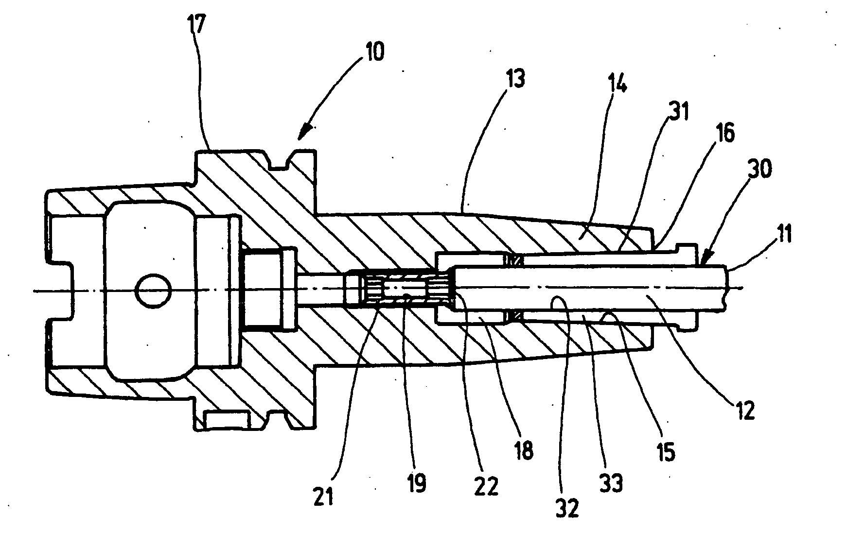
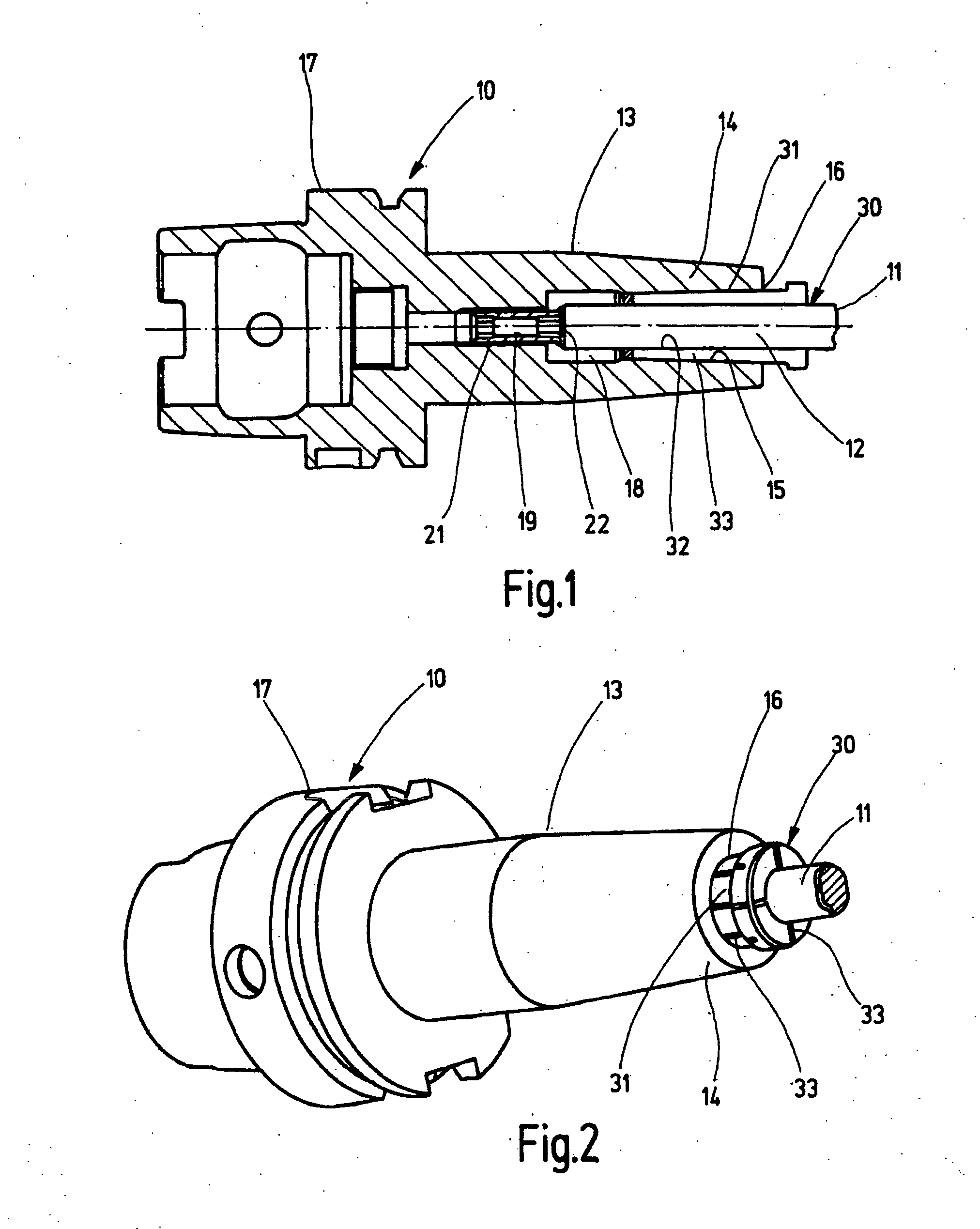
[0011] The drawings schematically depict a tool holder 10 for shrink-fit attachment of rotating tools 11, showing only the shaft 12 that is clamped in the tool holder 10. The tool holder 10 has a chuck 13 whose clamping section 14 has a central, conical receiving bore 15 that is open at the end 16 on the right in the drawing, and is used for insertion and accommodation of an insert 30. Adjoining the clamping section 14, the tool holder 10 has an end region 17, which is not important to the invention and can be embodied in any way a designer sees fit. With this end region 17, the tool holder 10 can be inserted in a known way, for example into a working spindle, not shown, of a machine tool. By contrast with the drawing, the end region 17 can also be embodied differently, depending on the given circumstances of the spindle. For example, it can also be embodied as a simple shaft, which is part of a separate chuck or can be detachably inserted along with the tool holder 10 into a separa...


PUM

PropertyMeasurementUnit
Angleaaaaaaaaaa
Forceaaaaaaaaaa
Depthaaaaaaaaaa

Abstract

The invention relates to a tool holder (10) for shrink-fit attachment of rotating tools (11) with predominantly cylindrical shafts (12), having a chuck (13) with a clamping section (14) containing a conical receiving bore (15) to accommodate an insert (30) that has a cylindrical bore (32) to accommodate the tool shaft (12) and has a conical outer surface (31 ) to be contained in the receiving bore (15) of the clamping section (14). The insert (30) is embodied so that after the axial insertion of the insert (30) into the hot chuck (13), a contact is produced between the insert (30) and the chuck (13) on the one hand and between the insert (30) and the inserted tool shaft (12) on the other hand and, when the chuck (13) cools, the tool shaft (12) is clamped, wherein it is possible to bridge over large diameter tolerances while achieving maximum clamping forces (FIG. 1).

Description

BACKGROUND OF THE INVENTION [0001] The invention relates to a tool holder for shrink-fit attachment of rotating tools with predominantly cylindrical shafts of the type described in the preamble to claim 1. [0002] In a known tool holder of this kind (U.S. Pat. No. 6,315,506 B1), the chuck is provided with a socket in the center for an insert; this central socket of the chuck has a cylindrical inner bore that widens out in an approximately conical fashion toward its open end. This socket can accommodate the entire length of an insert, which is correspondingly adapted to have one longitudinal segment with a cylindrical outer surface and an adjoining longitudinal segment with a conical outer surface, the two longitudinal segments being accommodated in a precisely fitting way inside the socket of the chuck. In the region of the cylindrical longitudinal segment, the insert has a threaded bore that is engaged by a coaxial threaded screw whose screw head is supported axially against the chu...

Claims


Application Information

Patent Timeline
IPC IPC(8): B23B31/117B23Q3/12B23B31/20B23P11/02
CPCB23B31/1179B23B31/20Y10T409/30952Y10T279/3487Y10T279/17957Y10T29/49865Y10T409/309408Y10T409/308624Y10T408/95B23B31/2073
Inventor VOSS, MICHAELWIELAND, HORST
Owner OTTO BILZ WERKZEUGFAB
Why Eureka
Try Eureka