Wellhead seal device to seal casing

a sealing device and wellhead technology, applied in the direction of well accessories, drilling accessories, fluid removal, etc., can solve the problem of taking a large force to energize the seal to the casing surface, and achieve the effect of less force and large diametric toleran

Active Publication Date: 2012-03-22
STREAM FLO INDS
View PDF12 Cites 15 Cited by
  • Summary
  • Abstract
  • Description
  • Claims
  • Application Information

AI Technical Summary

Benefits of technology

[0009]The wellhead seal device may be provided to seal the annular space formed between a central bore of vertically aligned upper and lower wellhead members and a rough casing. For example, the upper wellhead member may be a tubing head, and the lower wellhead member may be a casing head. However, the seal device might be accommodated in other wellhead members. The seal device has the advantage of providing, at its lower sealing portion, a primary seal to the rough casing, and a seal to the central bore of the lower wellhead member (ex. casing head), while providing at its upper sealing portion, an external metal seal to the central bore of the upper wellhead member (ex. tubing head), and an internal, secondary metal seal to the rough casing. The seal device includes an annular metal sealing sleeve configured to provide elastomeric or other seals at its lower sealing portion. The upper sealing portion of the annular metal sealing sleeve is configured to allow a secondary metal seal to the rough casing to be energized from above, with a downward force, prior to installing the upper wellhead member. This allows the wellhead seal device to be used in a wellhead with a threaded union between the lower and upper wellhead members (ex. casing head and the tubing head).
[0010]The outer surface of the casing, which is formed by rolling, is a rough un-finished surface, with large diametric tolerance. Thus, it takes a large force to energize a seal to this casing surface. However, the central bore of the upper and lower wellhead members typically have machine finished surfaces and tight tolerances, so seals to these surfaces require less force to energize. In one embodiment of the wellhead seal device, the primary and secondary seals to the rough casing are separated from the seals to the finished surfaces of the upper and lower wellhead members. As well, the primary and the secondary seals to the casing are both made by separate surfaces of the one seal device. By separating the seals in the manner, and by configuring the seal device such that the primary and secondary seals to the rough casing are energized from above, without the upper wellhead member yet in place, for example using vertical threaded seal energizing members, sufficient force can be applied to energize a secondary metal seal to the rough casing. A threaded connection between the upper and lower wellhead members can thereafter be made without concern for the primary and secondary seals to the rough casing. The seal device may alternatively be used with flanged or other wellhead connections, but it has the advantage of being able to form a secondary metal seal to the casing in a wellhead which uses a threaded connection.
[0011]Broadly stated, there is provided a wellhead seal device for sealing the annular space formed in a central bore extending through vertically aligned upper and lower wellhead members adjacent the rough outer wall of a tubular casing, the casing extending through the lower wellhead member and having an upper end in the upper wellhead member. The wellhead seal device includes an annular metal sealing sleeve having an upper portion integral with a lower portion. The lower portion has an inner bore adapted to provide an inner seal to the casing, and an outer surface adapted to provide an outer seal to the lower wellhead member. The upper portion is configured to extend upwardly from the lower portion into the central bore of the upper wellhead member. An outer tapered surface on the upper portion is adapted to form an external metal seal to a conical central bore section at a lower end of the upper wellhead member. An inner surface of the upper portion is adapted to be spaced from the casing in the upper wellhead member to form a sealing annulus. A metal seal ring having an outer conical surface is adapted to fit around the casing within the sealing annulus supported by the lower portion adjacent the casing. A wedge ring, adapted to fit around the casing above the metal seal ring, has an inner cam surface to engage the outer conical surface of the metal seal ring within the sealing annulus. A retaining ring is adapted to be retained in and to close the sealing annulus of the upper portion around the casing above the wedge ring. The retaining ring forms a plurality of vertical threaded ports extending there through for alignment with the wedge ring. A plurality of threaded seal energizing members are adapted to be threaded through the threaded ports to push downwardly on the wedge ring such that the metal seal ring is compressed radially inwardly to form an internal metal seal to the casing and thus seal the sealing annulus. The downward action on the wedge ring also transfers downward force to the lower portion to energize the inner and outer seals.

Problems solved by technology

Thus, it takes a large force to energize a seal to this casing surface.

Method used


Image

  • Wellhead seal device to seal casing
  • Wellhead seal device to seal casing
  • Wellhead seal device to seal casing

Examples


Embodiment Construction

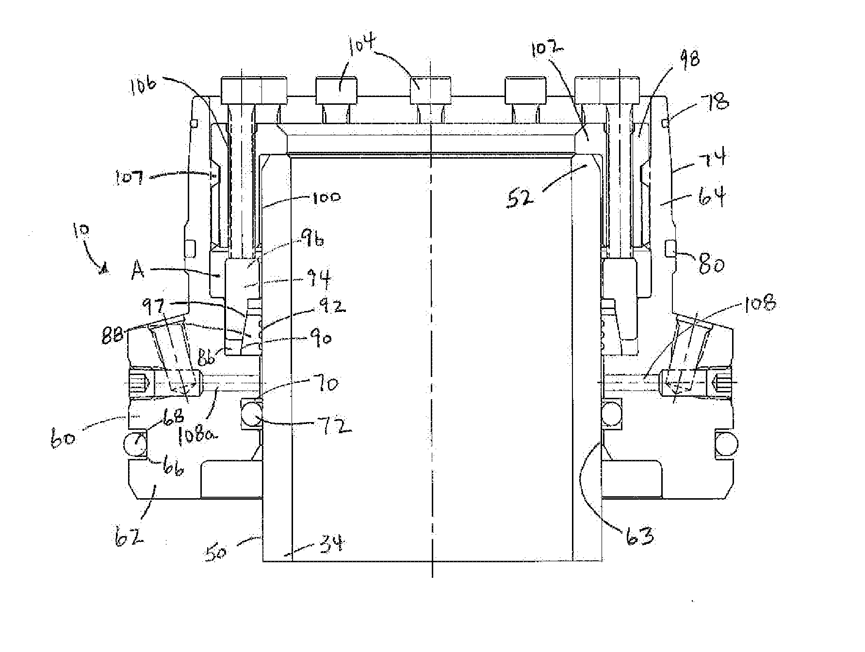
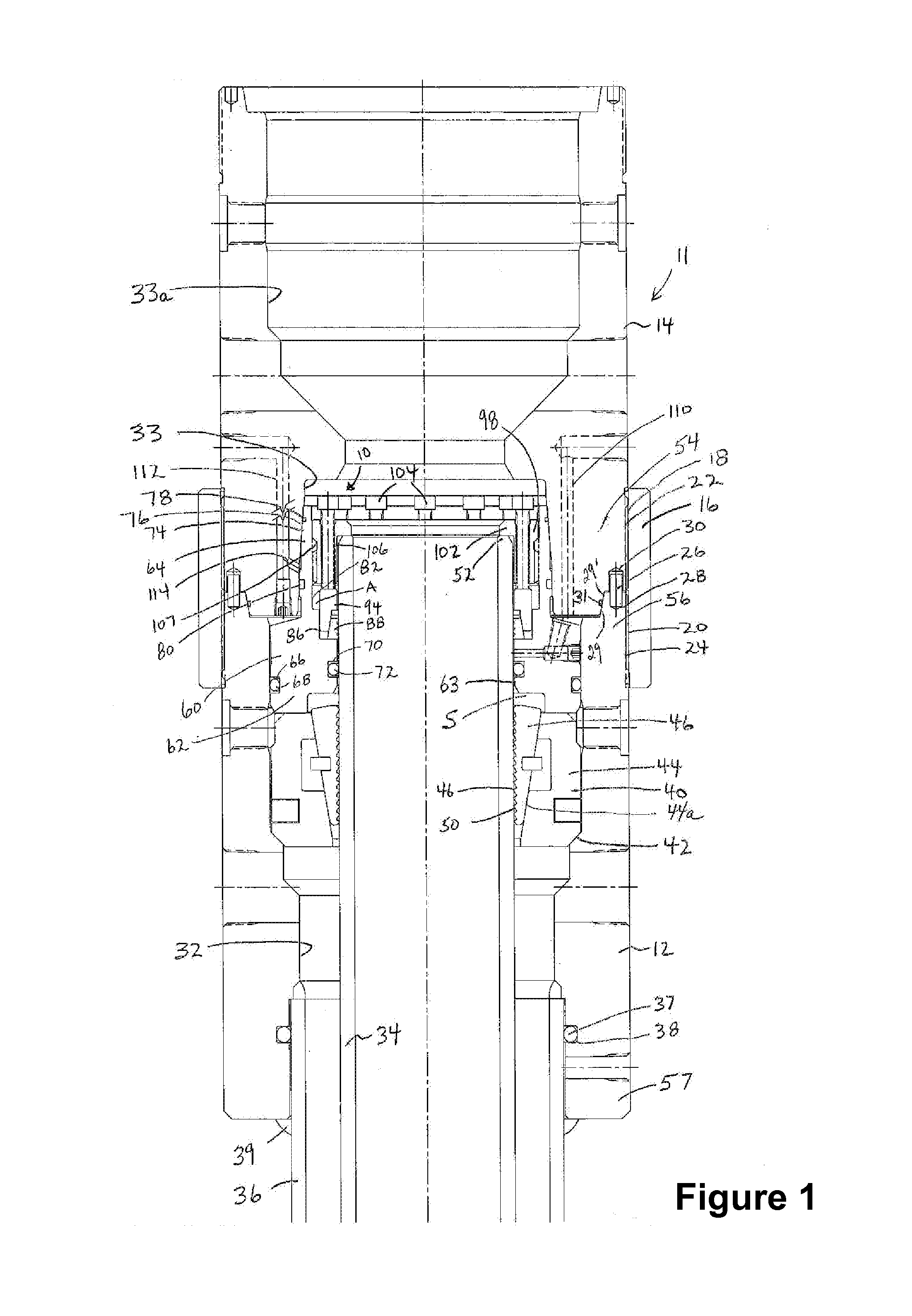
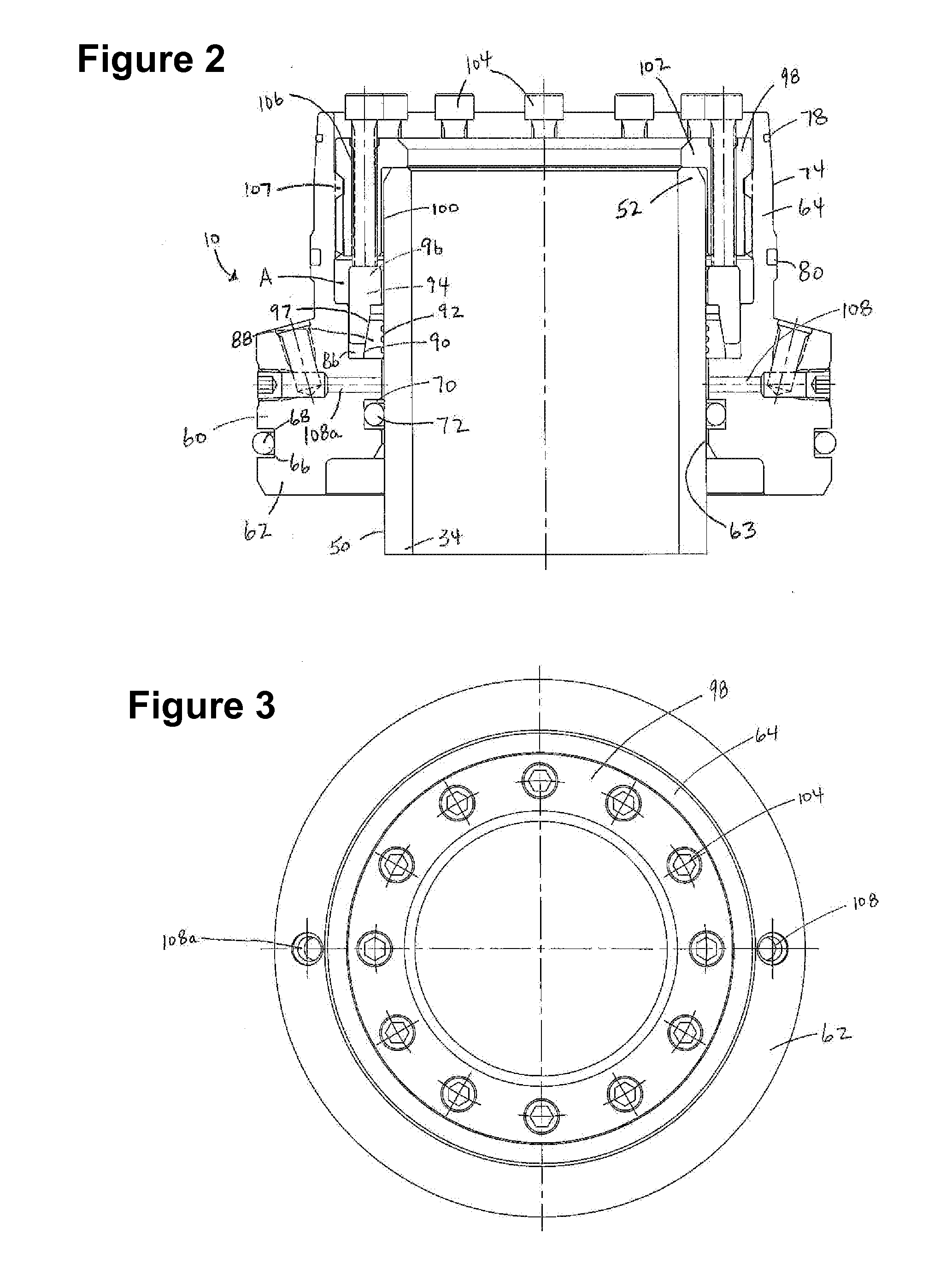
[0036]Having reference to FIGS. 1-3, one exemplary embodiment of the wellhead seal device 10 is shown in connected and sealing relationship in a wellhead assembly 11. A lower wellhead member, shown as a casing head 12, is connected to an upper wellhead member, shown as a tubing head 14. The connection between the wellhead members 12, 14 is shown as a threaded collar 16, although other known pressure containing wellhead connections may be used, such as other threaded connections, top and bottom bolted flanges, bolted up or down stud connectors, hub connectors or welded connections. The threaded collar 16 is formed with a set of left-hand threads 18 and a set of right-hand threads 20 on its inner surface. Threads 18, 20 provide a threaded connection to the threads 22 on the lower end 54 of the tubing head 14, and to the threads 24 on the upper end 56 of the casing head 12. This type of threaded connection is described in greater detail in United States Published Patent Application 200...


PUM


Abstract

A wellhead seal device forms metal seals in an annular space between inner and outer tubular members such as a rough casing held within aligned casing and tubing heads. An annular metal sealing sleeve has a lower portion seated in the annular space, and an upper portion which forms an inner sealing annulus adjacent the outer wall of the inner tubular member. A metal seal ring and a wedge ring are located in the inner sealing annulus. A retaining ring is retained by the upper portion above the wedge ring. Threaded seal energizing members extend through the retaining ring to push downwardly on the wedge ring and compress the metal seal ring radially inwardly to form a metal seal to the inner tubular member and thus seal the inner sealing annulus. The lower portion of the annular metal sealing sleeve may seal to the casing head and to the casing.

Description

CROSS-REFERENCE TO RELATED APPLICATION[0001]This application claims priority from U.S. Provisional Patent Application No. 61 / 385,299 filed Sep. 22, 2010, which is incorporated by reference herein to the extent that there is no inconsistency with the present disclosure.FIELD OF THE INVENTION[0002]This invention relates to a wellhead seal device for sealing an annular space between tubular members, for example for sealing the annular space formed in a central bore of vertically aligned upper and lower wellhead members adjacent the rough outer wall of a tubular casing extending through the lower wellhead member and ending in the upper wellhead member. The invention also relates to a wellhead assembly sealed with the wellhead seal device, and to a method of sealing a wellhead with the wellhead seal device.BACKGROUND[0003]A tubular casing string, termed “casing” is used when drilling wells to support the drill hole against collapse. Casing is hung with a casing hanger, or is otherwise su...

Claims


Application Information

Patent Timeline
Patent Type & Authority Applications(United States)
IPC IPC(8): E21B33/04E21B33/12
CPCE21B33/12E21B33/04
Inventor LANG, HEINRICHLAM, TONY M.GUO, TIANLE
Owner STREAM FLO INDS
Why Eureka
Try Eureka