Shaft of a gas-turbine engine, in particular a radial shaft or a shaft arranged at an angle to the machine axis

Inactive Publication Date: 2015-12-22
ROLLS ROYCE DEUT LTD & CO KG
View PDF22 Cites 5 Cited by
  • Summary
  • Abstract
  • Description
  • Claims
  • Application Information

AI Technical Summary

Benefits of technology

[0008]The object underlying the present invention is to provide a shaft of an aircraft gas-turbine engine, in particular a radial shaft which, wh

Problems solved by technology

The use of highly rigid fibers results

Method used


Image

  • Shaft of a gas-turbine engine, in particular a radial shaft or a shaft arranged at an angle to the machine axis
  • Shaft of a gas-turbine engine, in particular a radial shaft or a shaft arranged at an angle to the machine axis
  • Shaft of a gas-turbine engine, in particular a radial shaft or a shaft arranged at an angle to the machine axis

Examples


Example

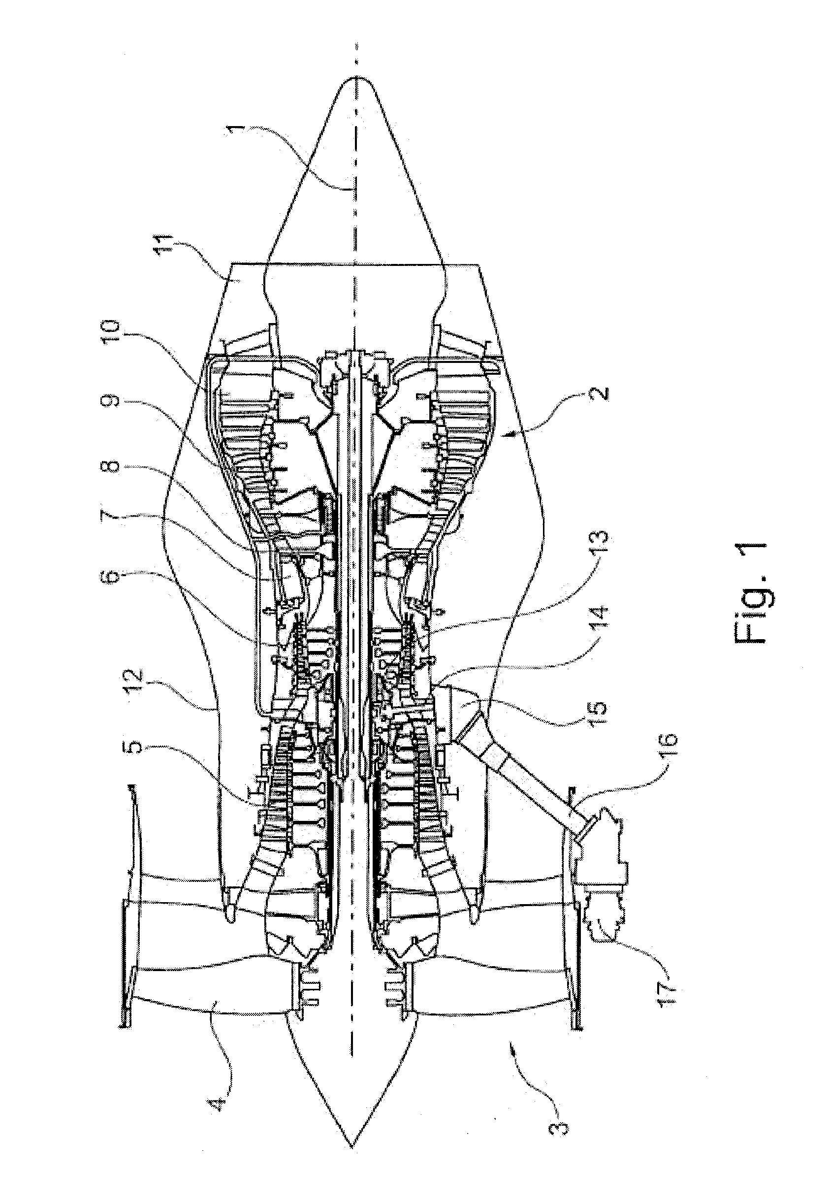
[0056]The gas-turbine engine 2 in accordance with FIG. 1 is a generally represented example where the invention can be used. The engine 2 is of conventional design and includes in the flow direction, one behind the other, an air inlet 3, a fan 4 rotating inside a casing, an intermediate-pressure compressor 5, a high-pressure compressor 6, a combustion chamber 7, a high-pressure turbine 8, an intermediate-pressure turbine 9 and a low-pressure turbine 10 as well as an exhaust nozzle 11, all of which being arranged about a center engine axis.

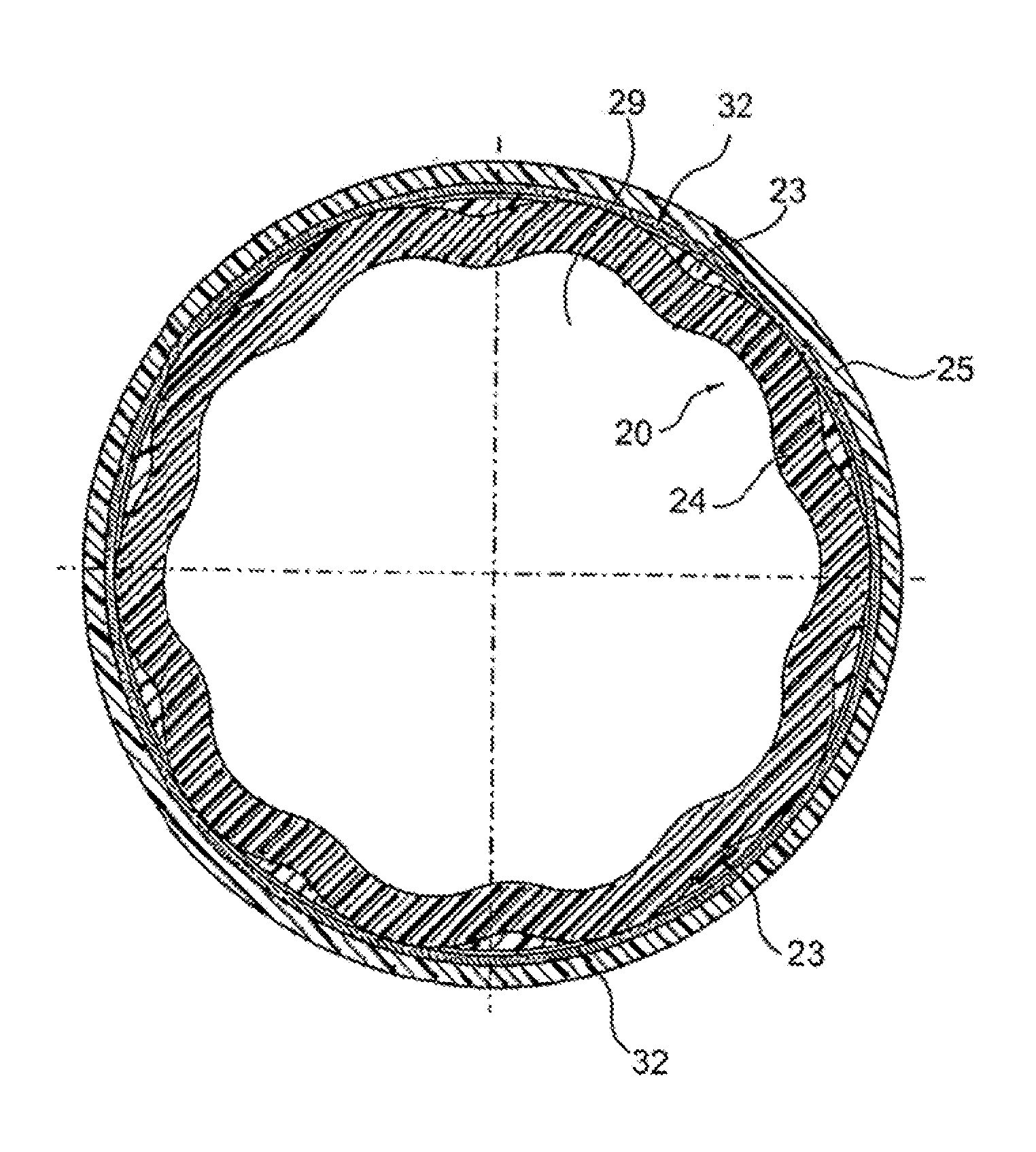
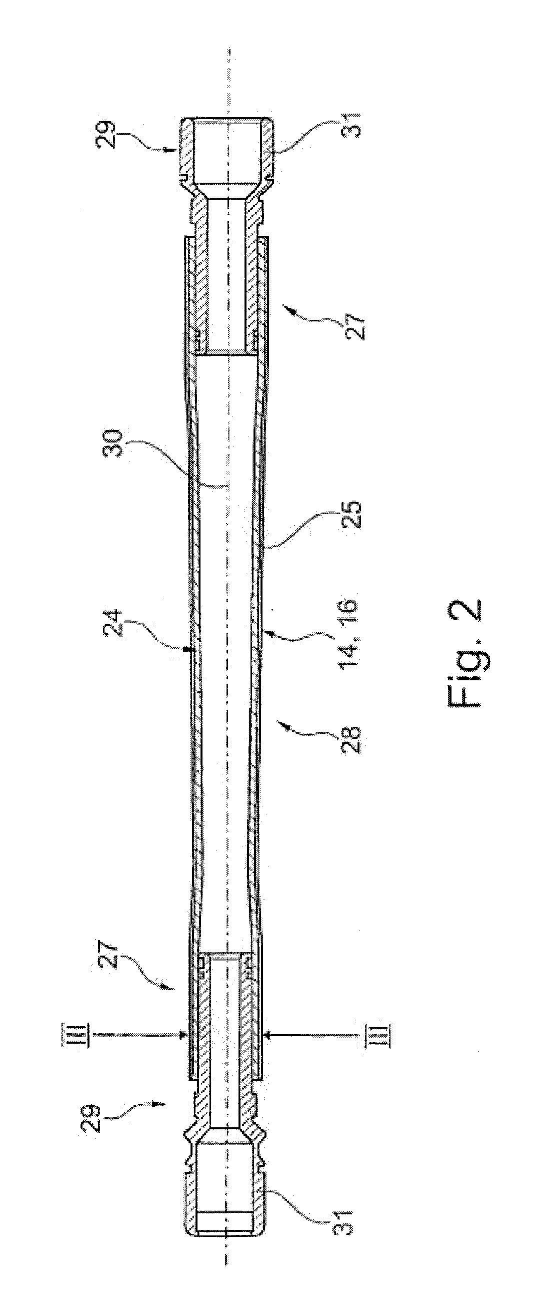
[0057]FIGS. 2 and 3 show an exemplary embodiment of the radial shaft in accordance with the invention, or of an engine shaft of the inventive type. The shaft is designed either as a radial shaft 14 or as a shaft 16 arranged at an angle and is used to connect a gear unit 13 (see FIG. 1) to a gear unit 15. The gear unit 15 can be operatively connected to auxiliary units. The shaft designed in accordance with the invention can also be designed in the ...


PUM

PropertyMeasurementUnit
Angleaaaaaaaaaa
Angleaaaaaaaaaa
Lengthaaaaaaaaaa

Abstract

A radial shaft of a gas-turbine engine which is made up of +/−45° layers, zero layers and +/−30° layers of carbon fiber composite and connected to load-input end pieces via sinusoidal connecting areas.

Description

[0001]This application claims priority to German Patent Application 102012022198.3 filed Nov. 13, 2012, the entirety of which is incorporated by reference herein.BACKGROUND[0002]This invention relates to a shaft of a gas-turbine engine, in particular a radial shaft or a shaft arranged at an angle to the machine axis.[0003]Radial shafts for gas-turbine engines are mostly made of metal. They are used to start the engine, where an electric motor or an air turbine installed in an external gearbox drives the radial shaft via a gear unit. This shaft is connected via a gear unit to the high-pressure compressor of the gas turbine. For starting, the high-pressure compressor is thus put into rotation in order to start the combustion process.[0004]During operation of the engine, the shaft is driven via the same connection in the reverse direction, in order to drive pumps and generators using an external gear unit.[0005]Shafts of this type are subject to the following requirements: firstly the ...

Claims


Application Information

Patent Timeline
IPC IPC(8): F16C3/00F16C3/02F01D5/06F01D5/28
CPCF01D5/282F16C3/026F01D5/06F05D2240/61F05D2300/603F05D2300/614F16C2360/23Y02T50/673Y02T50/672B29C70/462F05D2300/6034Y02T50/60
Inventor OESSENICH, RUEDIGERFREUND, ANDREASFILLER, MIRKORENNER, OLEPABST, ALEXANDER
Owner ROLLS ROYCE DEUT LTD & CO KG
Why Eureka
Try Eureka