Accessible control panel for overhead electrical apparatus in a suspended ceiling system

a technology of overhead electrical equipment and access control, which is applied in the installation of lighting conductors, instruments, signs, etc., can solve the problems of difficult service and reconfiguration, difficult to remove ceiling tiles, and often thwarted ceiling tile removal, so as to minimize labor costs and time. the effect of tim

Active Publication Date: 2010-07-29
NEXTEK POWER SYST
View PDF15 Cites 1 Cited by
  • Summary
  • Abstract
  • Description
  • Claims
  • Application Information

AI Technical Summary

Benefits of technology

[0007]Thus, ready and rapid access, especially for routine maintenance and repair, is provided to the electrical apparatus. Removal of the ceiling tile is not thwarted, because the electrical apparatus does not block such movement. The electrical apparatus does not rest directly on top of the ceiling tile, nor is the electrical apparatus positioned so closely to the ceiling tile that only limited movement of the ceiling tile is enabled. It is unnecessary to move equipment and / or cables in the plenum out of the way of the electrical apparatus to gain access to the electrical apparatus, thereby minimizing labor cost and the time needed to effect infrastructure service.

Problems solved by technology

As a result, the overhead plenum is crowded with mechanical and electrical infrastructure services, which is often difficult to service and reconfigure, particularly due to the presence of a complex, maze-like network of cables in the plenum.
However, such access is not readily available due to the crowded environment of the plenum.
However, removal of the ceiling tile is often thwarted, because the electrical apparatus blocks such movement.
This is labor-intensive and time-consuming and represents an undesirable expense.

Method used


Image

  • Accessible control panel for overhead electrical apparatus in a suspended ceiling system
  • Accessible control panel for overhead electrical apparatus in a suspended ceiling system
  • Accessible control panel for overhead electrical apparatus in a suspended ceiling system

Examples


Embodiment Construction

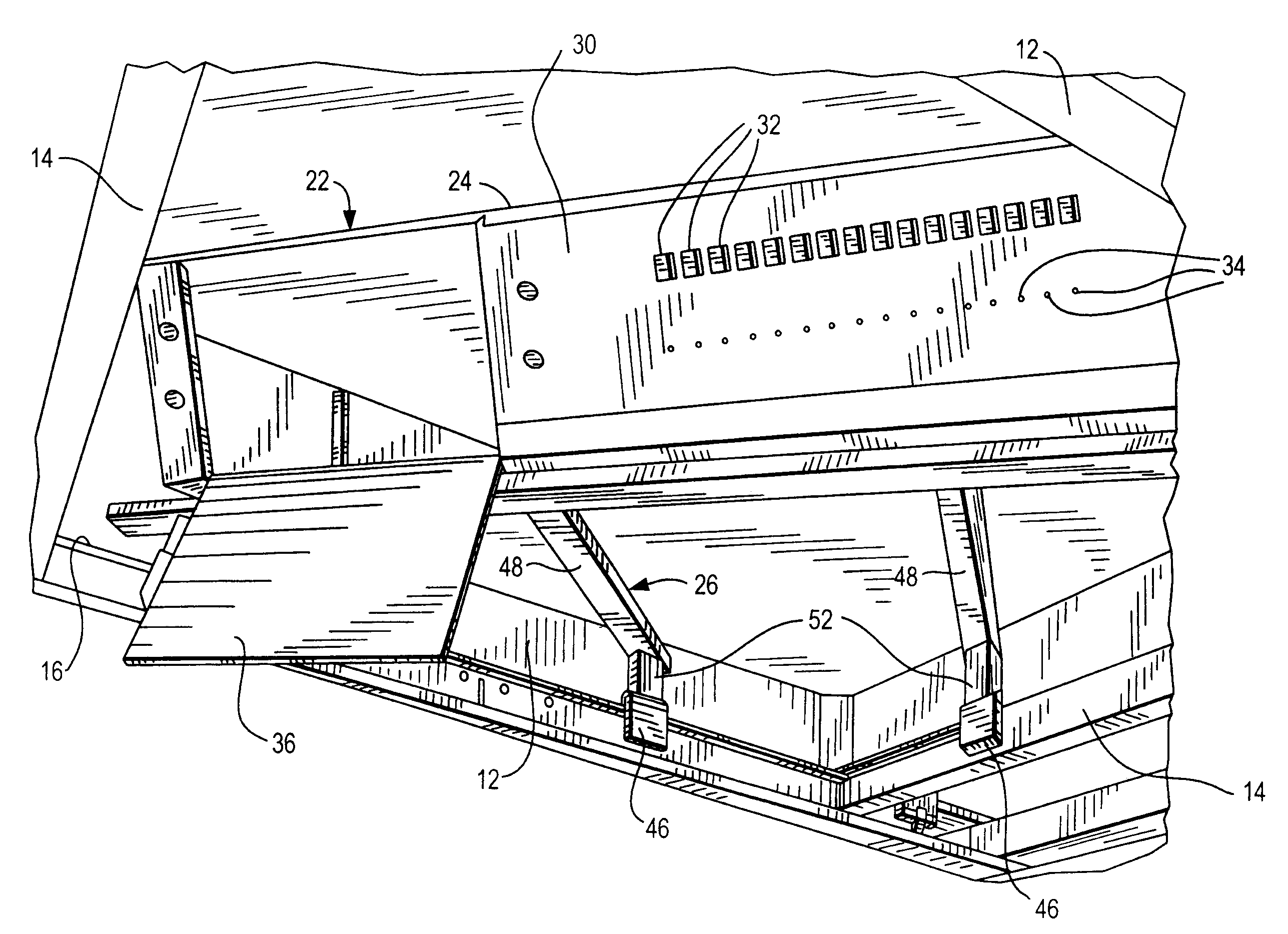
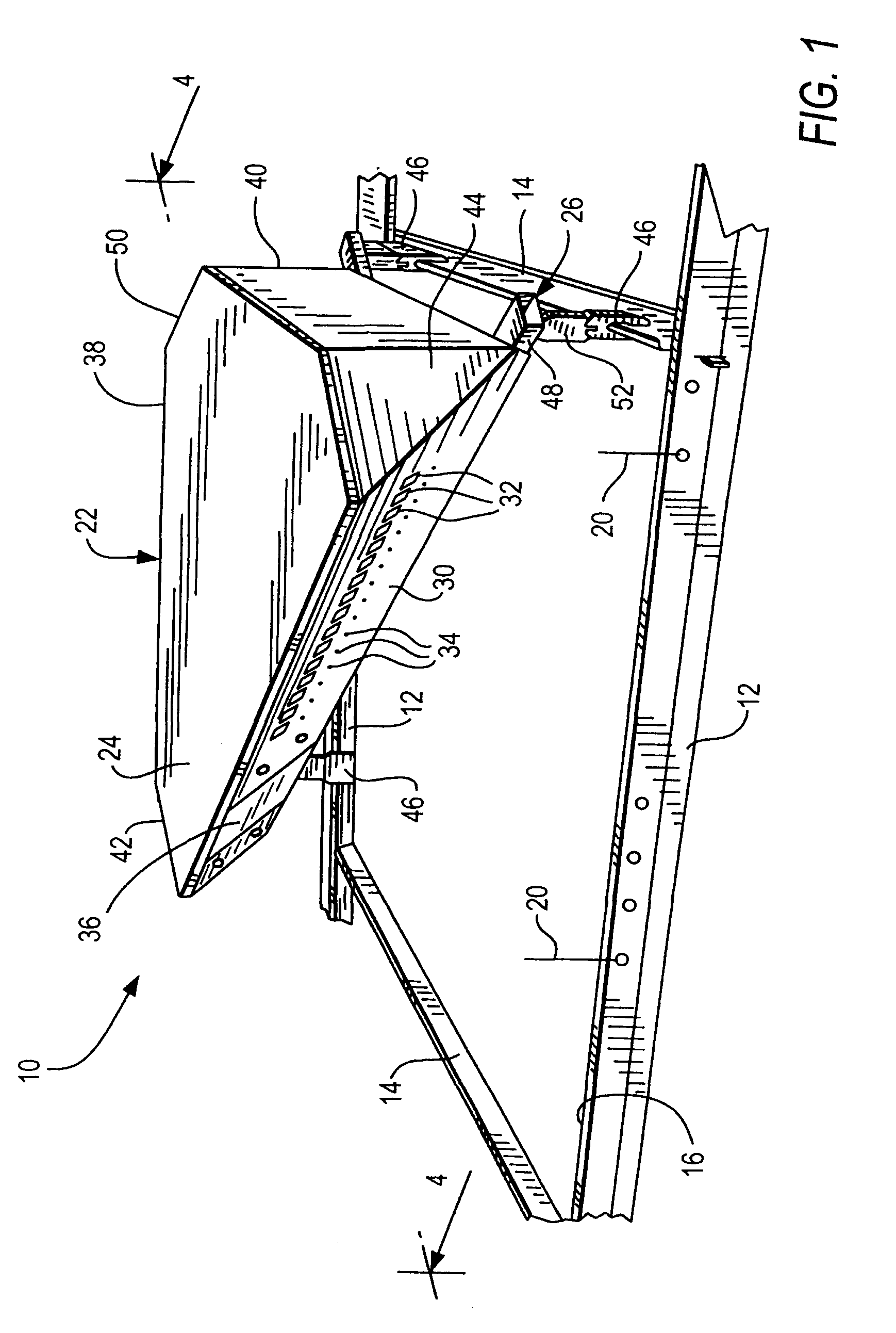
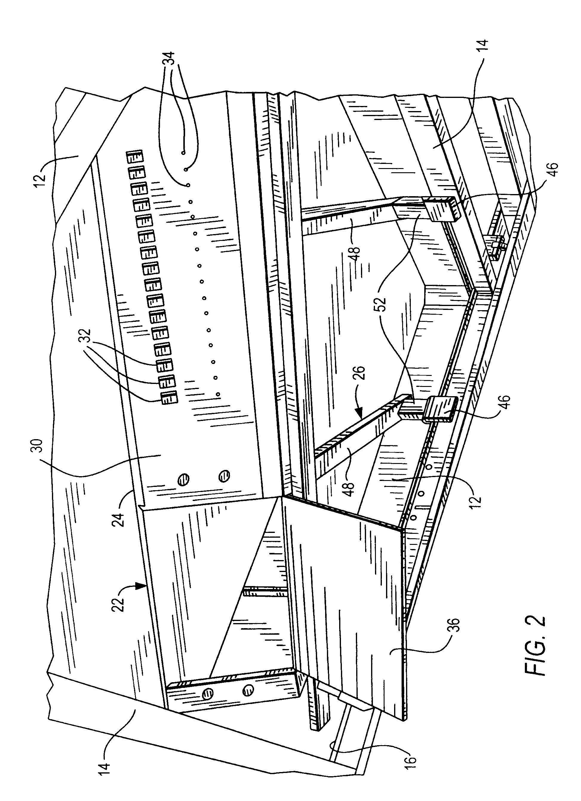
[0015]Reference numeral 10 in FIG. 1 generally identifies an overhead arrangement in a suspended or drop ceiling system having a rectangular grid framework of mutually orthogonal frame elements 12, 14 lying in a ceiling plane and bounding a plurality of openings 16 for supporting a corresponding plurality of ceiling members, e.g., ceiling tiles 18 (see FIG. 4). Each tile 18 has a complementary contour to that of its supporting opening 16. The frame elements 12, 14 are each preferably formed, e.g., by folding and stamping, from a single piece of sheet metal. Each frame element has a generally horizontal flange portion on which the tile 18 is supported around its periphery, and a vertical web portion. The openings 16 are preferably polygonal, e.g., square or rectangular in shape, each being typically sized at 2 feet by 2 feet, or 2 feet by 4 feet, or 4 feet by 4 feet, standards. Ceiling members, such as light fixtures, air ducts, loudspeakers and the like, other than tiles 18, could a...


PUM


Abstract

An overhead arrangement, for use in a suspended ceiling system having a grid framework of frame elements lying in a ceiling plane and bounding a plurality of openings for supporting a corresponding plurality of ceiling members, includes an electrical apparatus, such as a DC power supply, a support for supporting the electrical apparatus on the framework at an elevation above one of the ceiling members supported in one of the openings, and a slanted control panel on the housing and having manually accessible controls and visually accessible displays. The slanted control panel is obliquely and downwardly inclined relative to the ceiling plane to enable manual access to the controls and visual access to the displays through the opening to the slanted control panel from below the framework after the ceiling member is at least partially removed from its opening without mechanical interference between the ceiling tile and the electrical apparatus.

Description

DESCRIPTION OF THE RELATED ART[0001]A conventional suspended or drop ceiling system in a building structure includes a grid framework of mutually orthogonal frame elements lying in a ceiling plane and forming a plurality of polygonal openings, typically quadrilateral, into which ceiling tiles, light fixtures, air ducts, loudspeakers and like ceiling members are inserted and supported. The ceiling system provides, among other things, a visual, and often acoustic, barrier to building infrastructure, such as sprinkler pipes, water pipes, air conditioning duct work, electrical conduits, electrical power cables, telephone cables, computer network cables, cable trays, electrical junction boxes, as well as other mechanical and electrical services, routinely mounted in an overhead plenum or space between a real ceiling of the building structure and the suspended framework.[0002]As a result, the overhead plenum is crowded with mechanical and electrical infrastructure services, which is often...

Claims


Application Information

Patent Timeline
Patent Type & Authority Applications(United States)
IPC IPC(8): G12B9/10E04C2/52E04B1/00
CPCE04B9/006E04B9/003
Inventor PARIGORIS, RONALD J.GUTSCHOW, WAYNE A.HARTMAN, BENJAMIN
Owner NEXTEK POWER SYST
Why Eureka
Try Eureka