Seal cavity protection
- Summary
- Abstract
- Description
- Claims
- Application Information
AI Technical Summary
Benefits of technology
Problems solved by technology
Method used
Image

Examples
Embodiment Construction
[0017]The present invention will now be described, by way of example only, and with reference to the accompanying drawing.
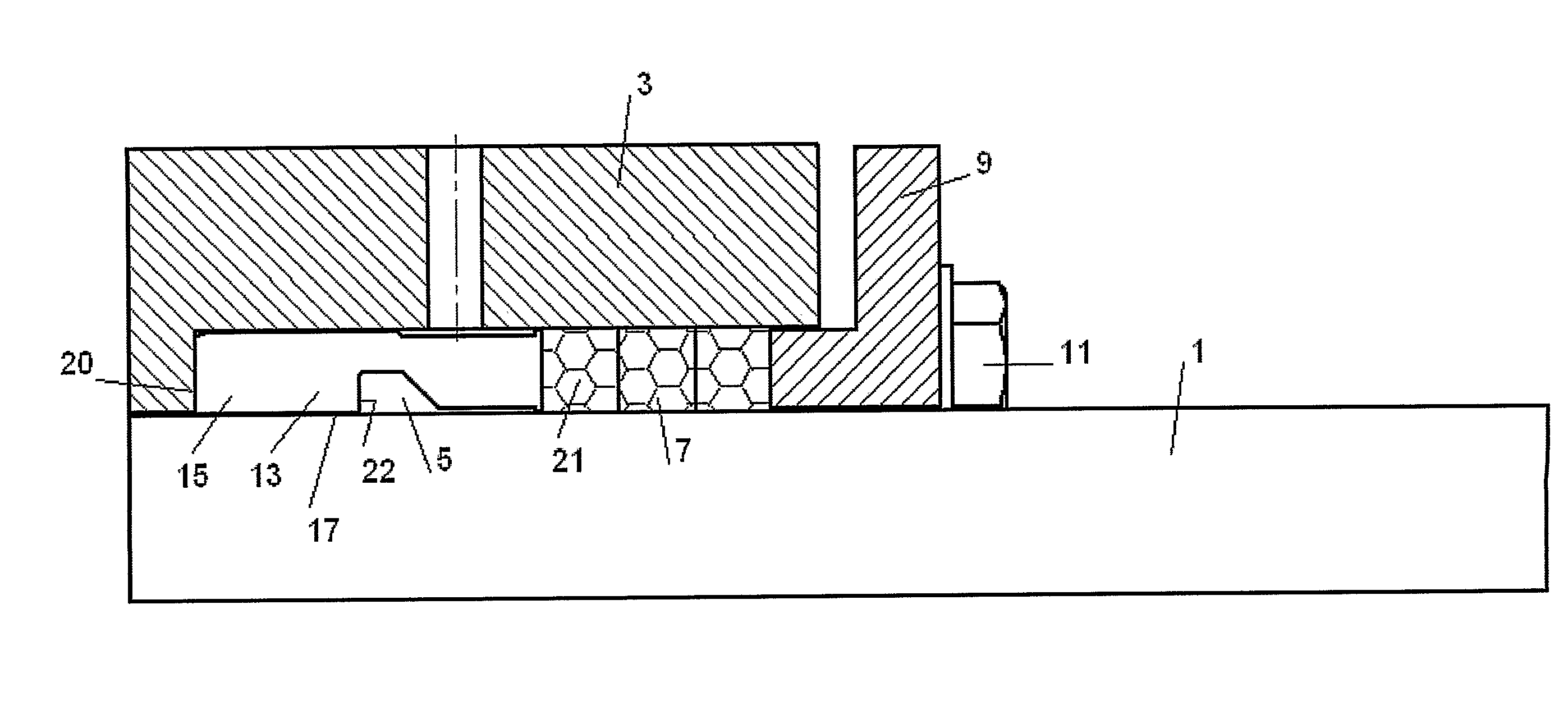
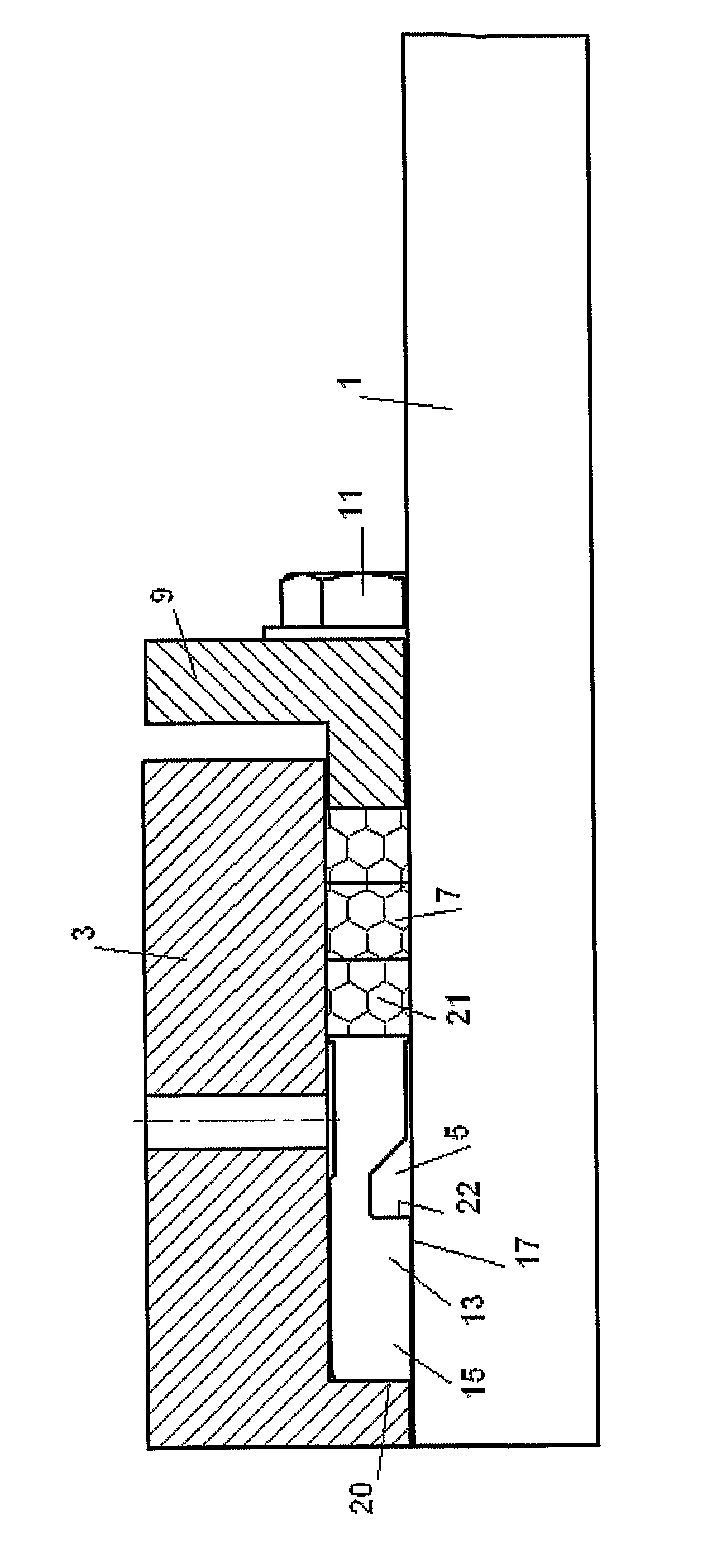
[0018]The rotary equipment shown in the accompanying drawing includes a shaft 1 which is free to circumferentially rotate and an equipment housing 3 which is circumferentially stationary.
[0019]Between equipment housing 3 and shaft 1 is a sealed cavity 5 which is further defined by seal means in the form of a series of packing rings 7 and a gland ring 9 and secured to the housing 3 by bolts 11.
[0020]Also occupying the seal cavity is a throat bushing 13 which comprises an annular element 15 adapted for a tight fit in the housing 3 and being located at an entrance to cavity 5 opposite the end occupied by the packing rings.
[0021]Annular element 15 of throat bushing 13 has a radially inner cylindrical surface 17 with a diameter greater than that of shaft 1, thereby defining a gap therebetween.
[0022]Throat bush 13 has a first annular face surface 20 which communicates ...
PUM
| Property | Measurement | Unit |
|---|---|---|
| Diameter | aaaaa | aaaaa |
Abstract
Description
Claims
Application Information
 - R&D
- Intellectual Property
- Life Sciences
- Materials
- Tech Scout
- Unparalleled Data Quality
- Higher Quality Content
- 60% Fewer Hallucinations
Browse by: Latest US Patents, China's latest patents, Technical Efficacy Thesaurus, Application Domain, Technology Topic, Popular Technical Reports.
© 2025 PatSnap. All rights reserved.Legal|Privacy policy|Modern Slavery Act Transparency Statement|Sitemap|About US| Contact US: help@patsnap.com