
Support Member

a support member and support technology, applied in the field of chairs and supports, can solve the problems of back bend or twist, office chairs and other chairs reject designs, uneven support to users, etc., and achieve the effect of adding strength or rigidity

Active Publication Date: 2010-07-29
KNOLL INC
View PDF31 Cites 5 Cited by
  • Summary
  • Abstract
  • Description
  • Claims
  • Application Information

AI Technical Summary

Benefits of technology

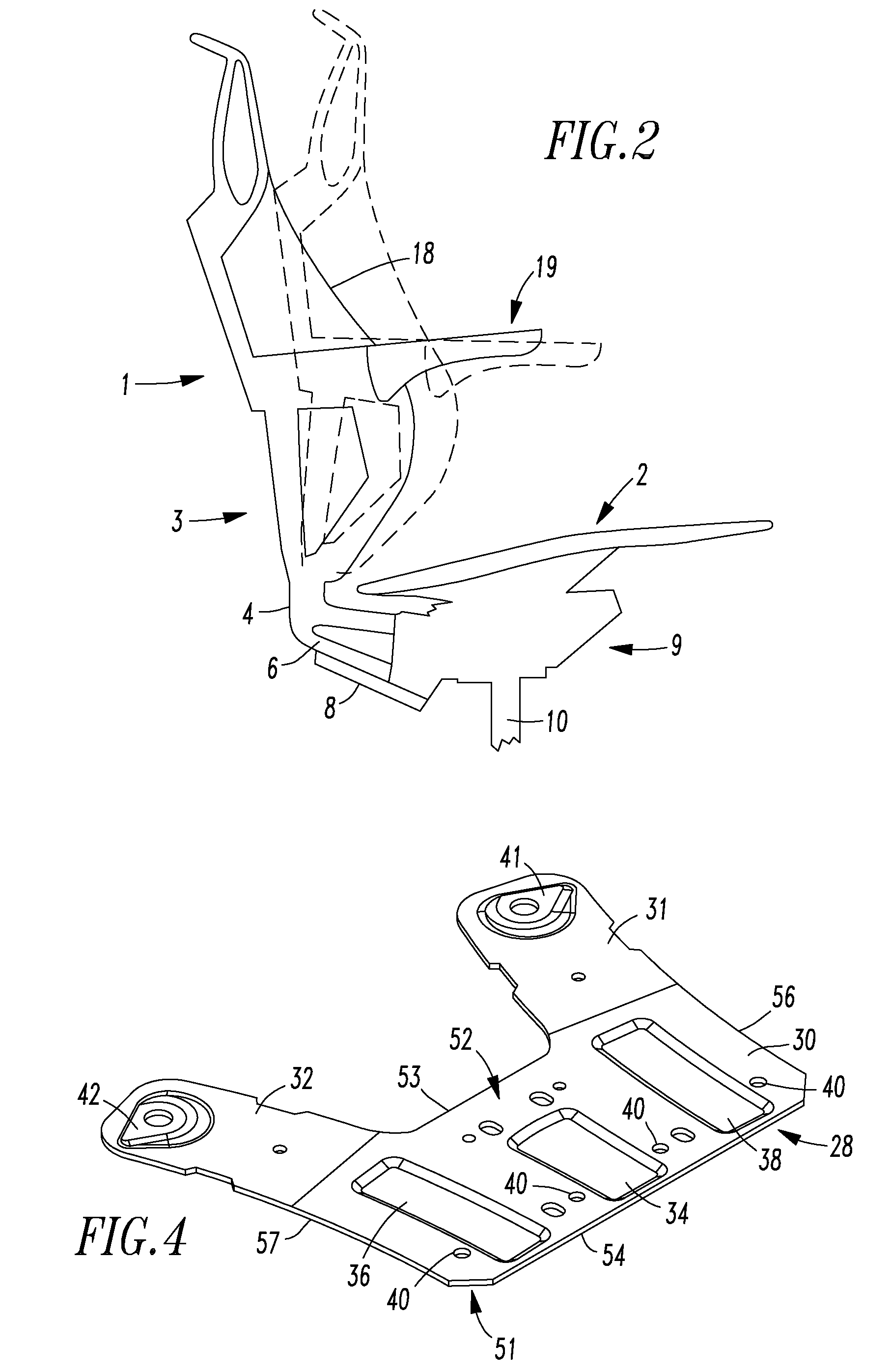
[0008]The support member may have one or more recesses or ribs formed in the plate portion. The ribs or recesses may also be formed in other portions of the support member. It should be appreciated such recesses or ribs may be configured to provide additional strength or rigidity to the support member.

Problems solved by technology

Often, fabricators and designers of office chairs and other chairs reject designs that utilize a reclinable back frame construction that does not incorporate multiple pivot points or multiple moveable rigid linkages.
However, such deforming components can provide uneven support to a user such that the back may bend or twist upon recline.
Such bending and twisting of the back can reduce the effective life of the chair and also provide an uncomfortable ride to a user.
Moreover, such deformable components may provide a “hard stop” upon reclining such that the ride of the chair during recline is not smooth.
Many users find such “hard stops” uncomfortable or undesirable.
At least because of the aforementioned problems, back designs that do not utilize pivots defined in a base or seat frame to recline a chair back are often not even conceived, let alone considered.

Method used


Image

  • Support Member
  • Support Member
  • Support Member

Examples


Embodiment Construction

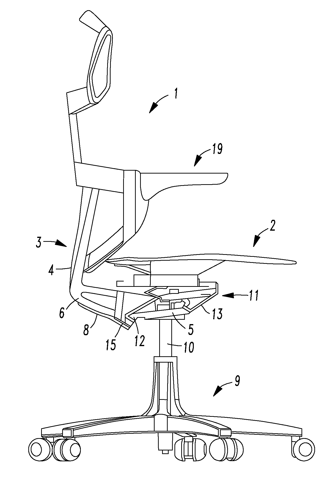
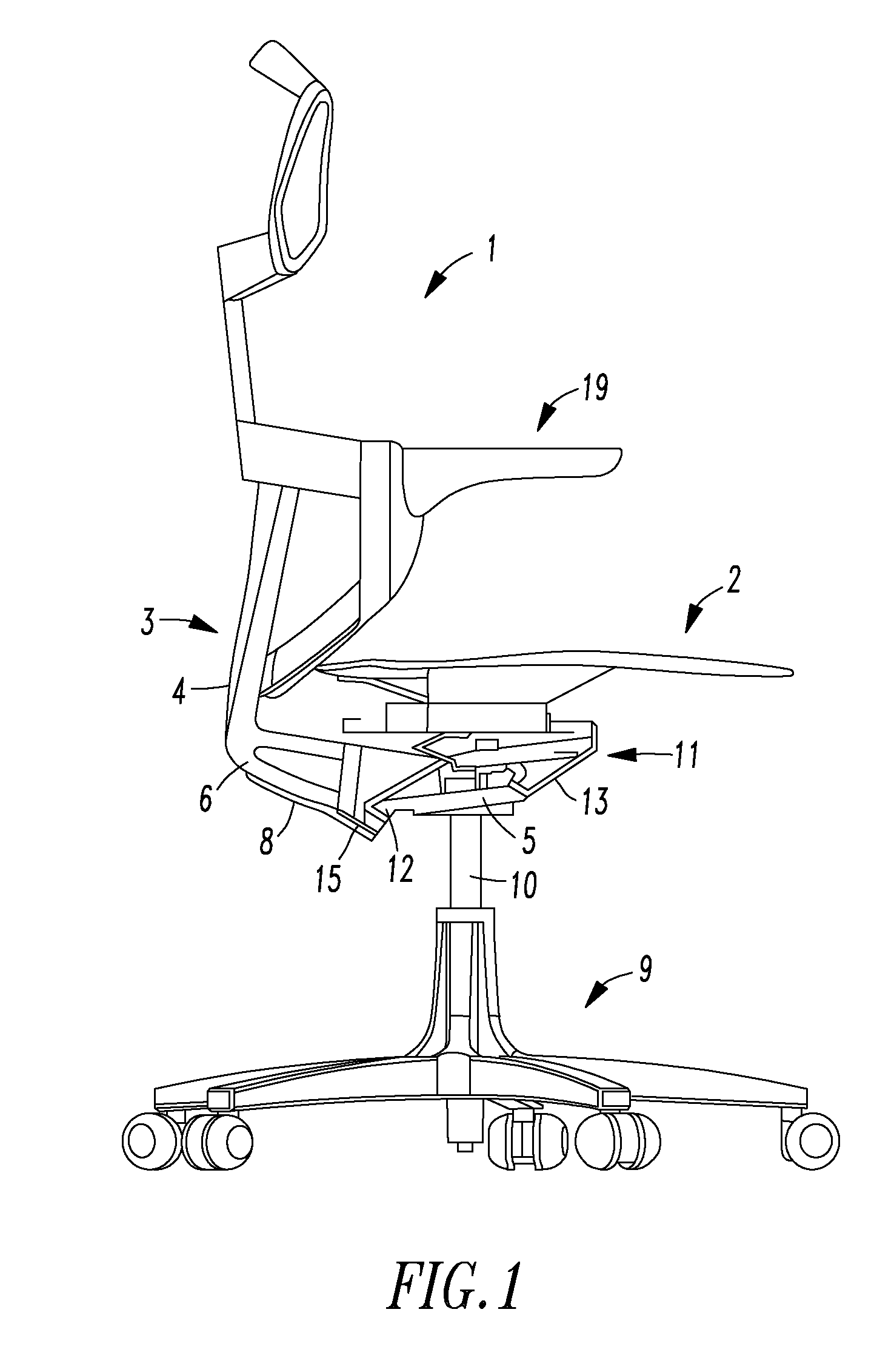
[0023]A first present preferred embodiment of a chair 1 is illustrated in FIGS. 1-3. The chair 1 includes a back assembly 3 and a seat assembly 2. The back assembly 3 includes a back frame 4 that is attached to an extension 6 and a back skin 18. The extension 6 may be integral with the back frame 4 or be fastened or otherwise connected to a portion of the back frame 4. The back frame 4 and extension 6 may be composed of an elastomeric material, plastic, metal or other material. The back skin 18 is attached to the back frame 4 and is configured to engage and support the back of a seated user. The back skin 18 may be composed of various materials such as mesh, fabric or elastomeric material.

[0024]The chair 1 also includes a base 9. The base is attached to the seat assembly 2 and the back assembly 3. The base 9 includes a pedestal 10 attached to a control mechanism 11. The pedestal 10 may include a gas cylinder or other column configured for height adjustment of the chair 1. The contro...


PUM


Abstract

A support member configured for attachment to a back assembly and a chair component is disclosed. One disclosed embodiment of the support member may be included in a chair that includes a base, a back assembly and the support member. The back assembly includes an extension attached to a back frame. The extension is attached to the base such that the back assembly is moveable relative to the base. The support member is attached to the extension and the base. The support member is more rigid than the extension. Preferably, the extension is composed of elastomeric material.

Description

FIELD OF INVENTION[0001]The present invention relates to chairs and supports for chair components.BACKGROUND OF THE INVENTION[0002]Chairs are often configured to have a back support that can be reclined. For instance, U.S. Pat. Nos. 4,328,943, 4,380,352, 4,533,177, 5,154,438, 5,601,337, 5,683,139, 5,909,923, 5,944,382, 6,386,634, 6,669,292, 6,767,066, 6,817,667, 6,869,142, 6,910,736, 6,913,315, and 7,273,253, U.S. Patent Application Publication Nos. US 2007 / 0000111, 2005 / 0093354, 2005 / 0052061 and 2004 / 0189073 and World Intellectual Property Publication No. WO 2008 / 041868 disclose chairs that include such a back support.[0003]Recently, chairs have been designed to be made of recycled materials or materials capable of being recycled, such as frame structures composed of plastic. For instance, a back frame or seat frame may be composed of plastic and attached to a base composed of plastic or metal. It is often desirable to have a reclinable back in such chairs. The reclinable back ofte...

Claims


Application Information

Patent Timeline
Patent Type & Authority Applications(United States)
IPC IPC(8): A47C3/00F16M13/02
CPCA47C7/445
Inventor GOLYNSKY, ARKADY
Owner KNOLL INC
Learn More