Driver circuit

a technology of driving circuit and drive shaft, which is applied in the direction of electronic commutators, electric programme control, dynamo-electric converter control, etc., can solve the problems of redundant power consumption and redundant current applied to the coil

Active Publication Date: 2010-07-29
SEMICON COMPONENTS IND LLC
View PDF7 Cites 13 Cited by
  • Summary
  • Abstract
  • Description
  • Claims
  • Application Information

AI Technical Summary

Benefits of technology

[0008]According to one aspect of the present invention, there is provided a driver circuit which supplies a motor drive current to two coils of a stepping motor. A rotor is rotated by the coils by setting different phases for the motor drive currents to the two coils. During a phase where a first coil of the two coils is in a high-impedance state, an induced voltage generated in the first coil is detected, and amounts of the motor drive currents supplied to the two coils are controlled according to a state of the detected induced voltage.

Problems solved by technology

This means that a redundant current is applied to the coil and redundant power is consumed.

Method used


Image

  • Driver circuit
  • Driver circuit
  • Driver circuit

Examples


Embodiment Construction

[0027]Preferred embodiments of the present invention will now be described with reference to the drawings.

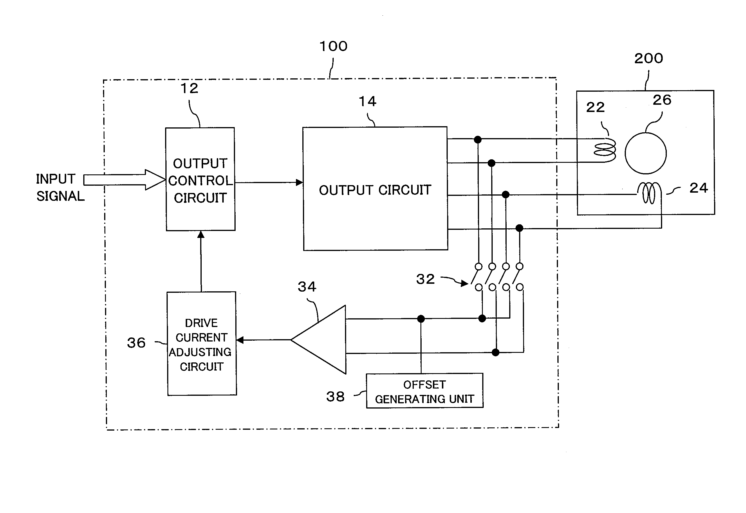
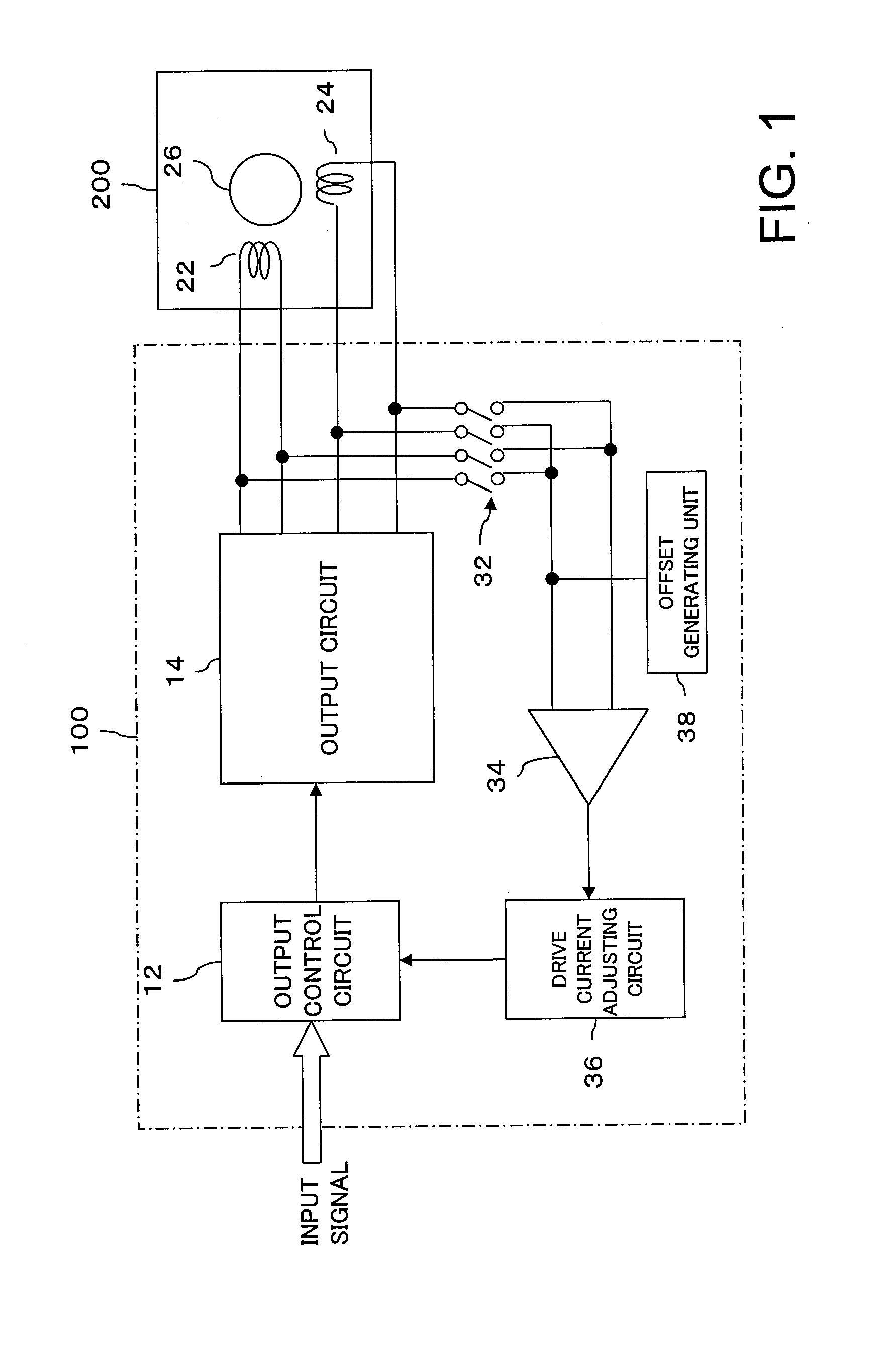
[0028]FIG. 1 is a diagram showing an overall structure of a system, and the system comprises a driver 100 and a motor 200. An input signal is input to the driver 100, and the driver 100 supplies a drive current corresponding to the input signal to the motor 200. In this manner, rotation of the motor 200 is controlled according to the input signal.

[0029]The driver 100 has an output control circuit 12, and the input signal is supplied to the output control circuit 12. The output control circuit 12 determines a drive waveform (phase) of a predetermined frequency according to the input signal, determines an amplitude of the drive current through PWM control, and generates a drive control signal. The generated drive control signal is supplied to an output circuit 14.

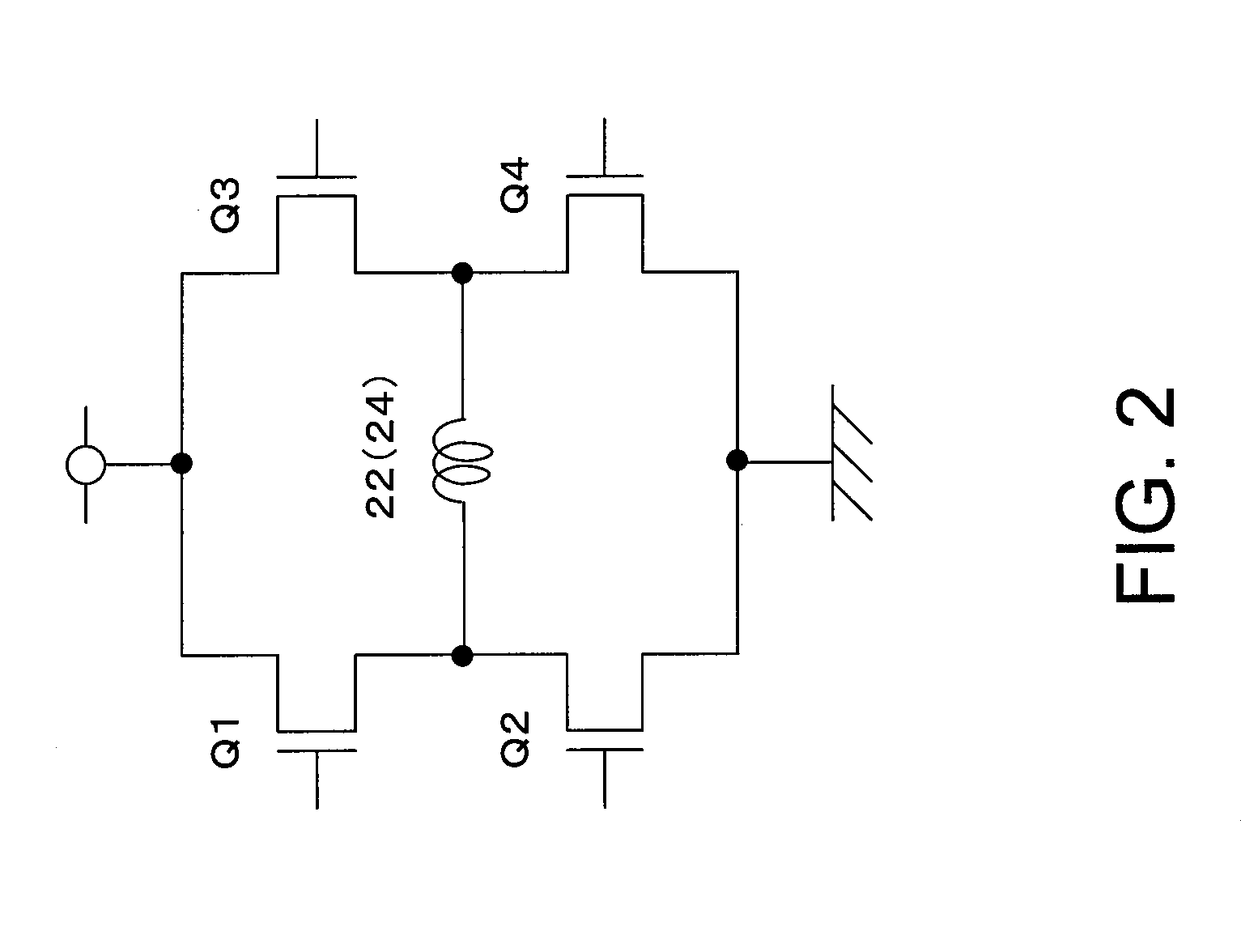
[0030]The output circuit 14 comprises a plurality of transistors, and a current from a power supply is controlled by sw...


PUM


Abstract

An amount of a motor drive current is controlled to an appropriate value. Two coils are provided, and a rotor is rotated by the coils by setting different phases for the supplied currents to the two coils. During a phase where one of the coils is in a high-impedance state, an induced voltage generated in the coil is detected. According to the state of the induced voltage, an output control circuit controls the amounts of the motor drive currents supplied to the two coils.

Description

CROSS-REFERENCE TO RELATED APPLICATIONS[0001]The entire disclosure of Japanese Patent Application Nos. 2009-017246 and 2009-298091 including specification, claims, drawings, and abstract is incorporated herein by reference.BACKGROUND OF THE INVENTION[0002]1. Field of the Invention[0003]The present invention relates to a driver circuit of a stepping motor which includes two coils and which rotates a rotor which is driven by the coils by setting different phases of supplied currents for the two coils.[0004]2. Description of the Related Art[0005]Various motors are known. As a motor which can accurately determine a position, a stepping motor is known, and is widely in use in various devices. For example, the stepping motor is used for focusing in a camera, antivibration, positioning in a machine tool, etc. The demand for the stepping motor is especially high in OA devices which require a large current.[0006]The driving of the stepping motor is executed normally by changing a rotational ...

Claims


Application Information

Patent Timeline
Patent Type & Authority Applications(United States)
IPC IPC(8): G05B19/40H02P8/22
CPCG05B19/40H02P6/188H02P8/12H02P6/18H02P6/182H02P8/04H02P8/16
Inventor HIOKI, KOSAKUTAKAI, KAZUMASANAGANUMA, TAKESHINIWA, YOSHIHIRO
Owner SEMICON COMPONENTS IND LLC
Why Eureka
Try Eureka