Energy consumption measurement

Inactive Publication Date: 2010-07-29
KONINKLIJKE PHILIPS ELECTRONICS NV
View PDF17 Cites 48 Cited by
  • Summary
  • Abstract
  • Description
  • Claims
  • Application Information

AI Technical Summary

Benefits of technology

[0009]In an embodiment, the communication unit supplies an identifier uniquely identifying the associated one of the plurality of devices. This has the advantage that the controller knows what actual apparatus is used, and thus is able to provide energy consumption information with reference to the specific apparatus.
[0010]In an embodiment, the controller is mechanically integrated with the electricity meter. This has the advantage that the meter information is directly available.

Problems solved by technology

Climate change and global warming are key issues.

Method used


Image

  • Energy consumption measurement
  • Energy consumption measurement
  • Energy consumption measurement

Examples


Embodiment Construction

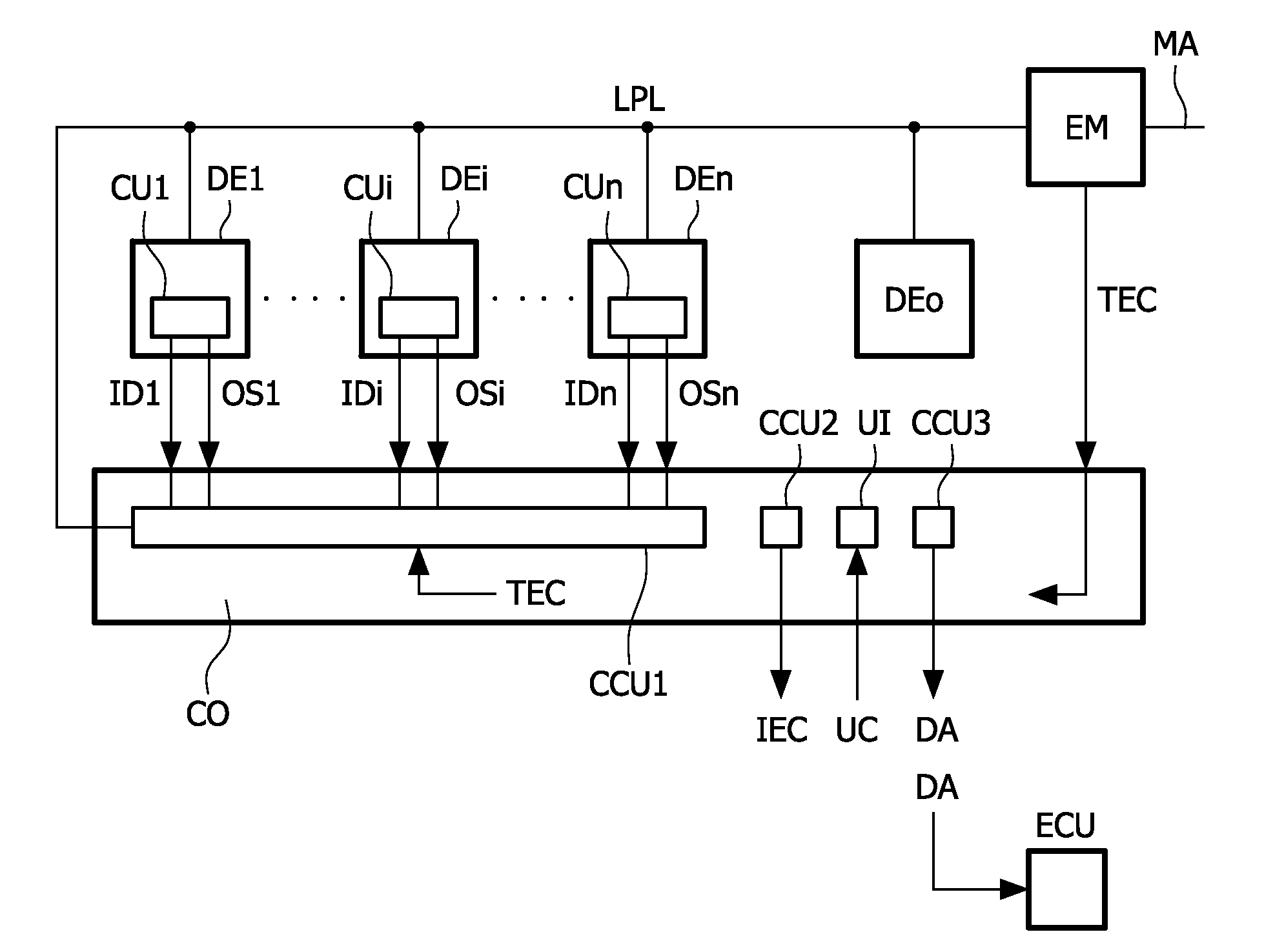
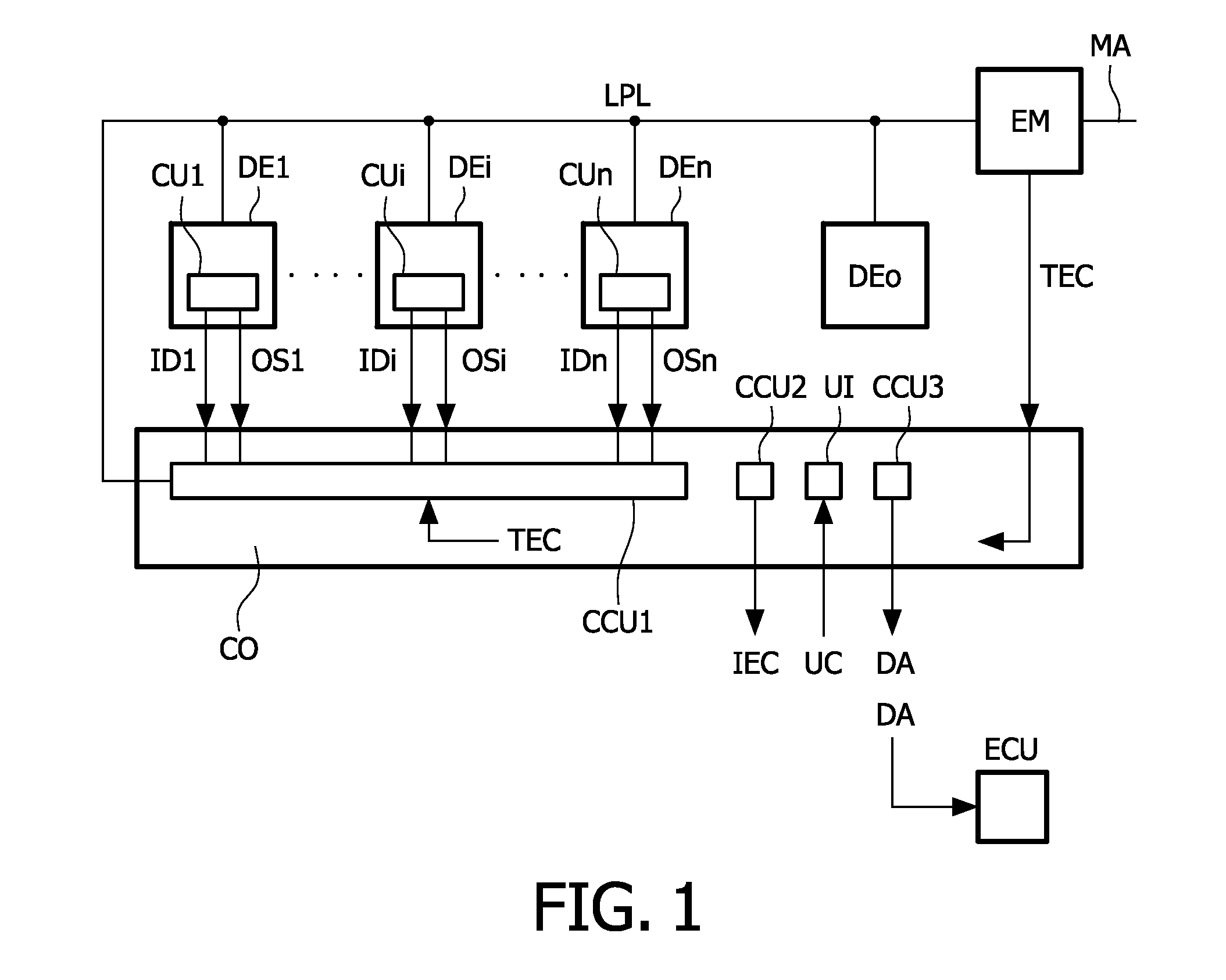
[0027]FIG. 1 schematically shows an embodiment of a system for measuring an energy consumption of a plurality of devices.

[0028]The system comprises a plurality of devices DE1, . . . , DEi, . . . , DEn which consume energy. It has to be noted that often a device which consumes energy is referred to as a device which consumes power. However, correctly speaking, power is energy per second. In the context of the present invention the term energy is used because it also covers power. Further, in the now following, if an item is referred to by one or more capital letters followed by a number, this number has to be considered to be an index. Thus DE1 or DEn refers to the particular device 1 or n. However, the index i is used to indicate the item in general, and thus DEi means any one of the devices DE1 to DEn, or the devices DE1 to DEn in general.

[0029]Each one of the devices DEi comprises a communication unit CUi (CU1, . . . , CUi, . . . , CUn) which provides operating status information ...


PUM


Abstract

A system for measuring energy consumption comprises a plurality of devices (DEi) of which at least a subset comprises a communication unit (CUi) for supplying operating status information (OSi) indicating an actual operating status with respect to an actual energy consumption of the associated one of the plurality of devices (DEi). A meter (EM) measures a total energy consumption (TEC) of the plurality of devices (DEi). A controller (CO) calculates an individual energy consumption (IEC) of a particular one of the plurality of devices (DEi) from a change of the total energy consumption (TEC) occurring at a change of the operating status of the particular one of the plurality of devices (DEi).

Description

FIELD OF THE INVENTION[0001]The invention relates to a system for measuring energy consumption, a controller for use in the system and a method of measuring energy consumption.BACKGROUND OF THE INVENTION[0002]Climate change and global warming are key issues. Consequently, a requirement exists to supervise energy consumption. Currently, in a standard household, electricity metering is done by a single meter which measures the sum of the energy consumption of all energy consuming devices in the household. The purpose of measuring the total energy consumption is to know how much to bill the consumer.[0003]U.S. Pat. No. 5,572,438 discloses an energy management and building automation system including a local area network or home automation data bus. Each load (energy consuming device) is connected to the bus via a control module which may contain a circuit breaker to disconnect the load from the mains upon command or upon occurrence of a power outage. The control modules may be a curren...

Claims


Application Information

Patent Timeline
Patent Type & Authority Applications(United States)
IPC IPC(8): G08C15/06
CPCG01R22/10Y04S20/40Y02B90/245G01D2204/14Y02B90/20Y04S20/30
Inventor REYMANN, STEFFENSIMONS, PAUL RICHARDCLARK, DAVID GEORGE
Owner KONINKLIJKE PHILIPS ELECTRONICS NV
Why Eureka
Try Eureka