Recording apparatus

a recording apparatus and a technology for recording, applied in the direction of typewriters, printing, other printing apparatus, etc., can solve the problems of air leakage, clogging of the nozzle, and deterioration of productivity, so as to prevent air leakage

Inactive Publication Date: 2010-07-29
SEIKO EPSON CORP
View PDF5 Cites 27 Cited by
  • Summary
  • Abstract
  • Description
  • Claims
  • Application Information

AI Technical Summary

Benefits of technology

[0032]According to the eighth aspect of the invention, it is possible reliably to prevent the air...

Problems solved by technology

In this instance, there is concern that the heat is transferred to the recording head located at the downstream side, which may cause a defect.
More specifically, there is concern that the ink remaining in nozzles of the recording head located at the downstream side may be dried by the heat to cause nozzle clogging.
Also, there is concern that vis...

Method used


Image

  • Recording apparatus
  • Recording apparatus
  • Recording apparatus

Examples


embodiment 1

Another Embodiment 1

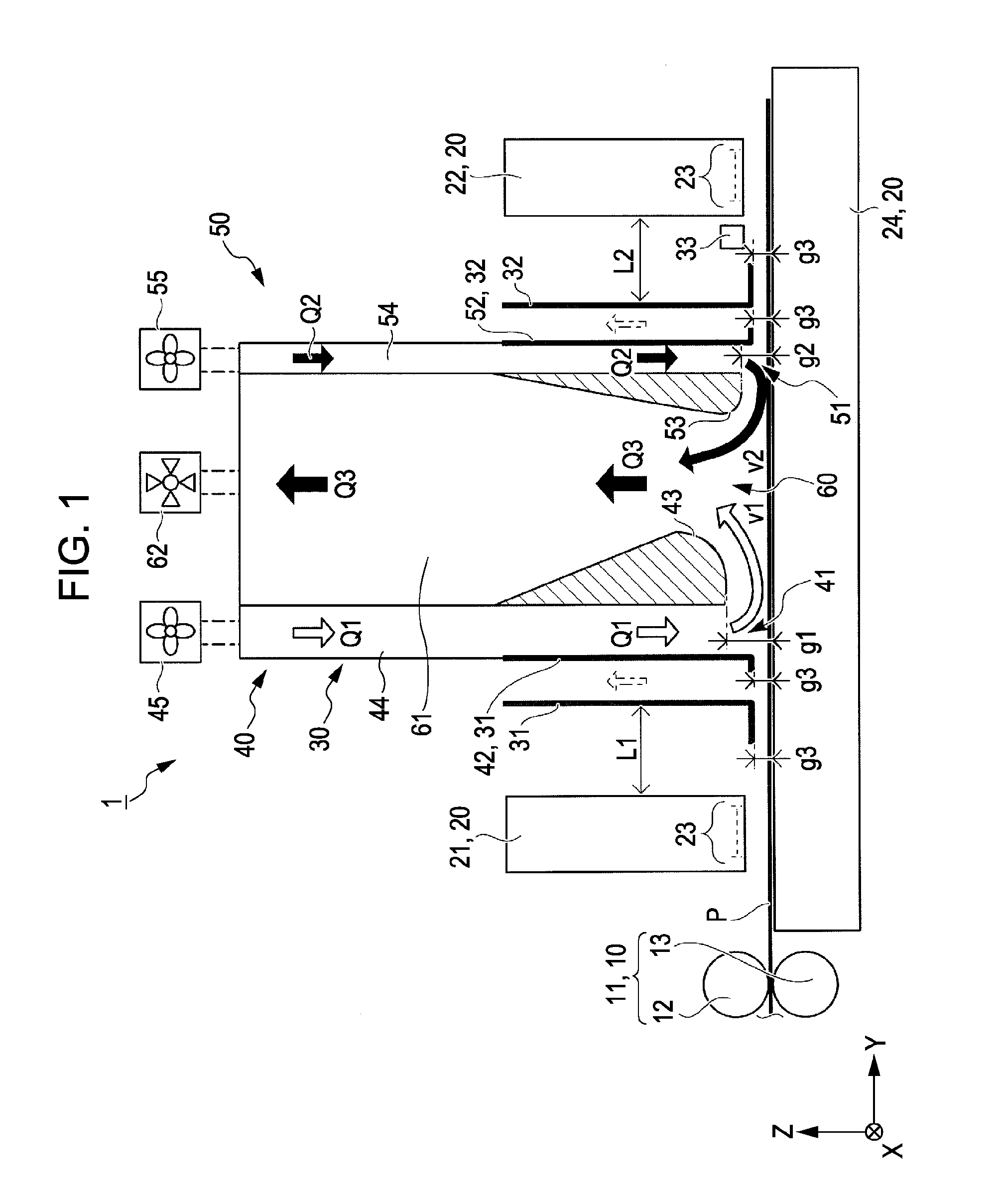
[0098]FIG. 2 is a side view schematically showing a printer according to anther embodiment 1.

[0099]As shown in FIG. 2, a platen 71 of a printer 70 according to another embodiment 1 includes a first heating platen 72, a cooling platen 75 and a second heating platen 73 in that order from an upstream side of the printer in a feed direction. Among the platens, the first heating platen 72 and the second heating platen 73 serve as the heating / drying unit 40. The cooling platen 75 serves as the cooling unit 50.

[0100]Except for components specifically described, other components are similar to those in the above-described embodiment, and thus the description thereof will be omitted.

[0101]The first heating platen 72 is extended from a position opposite to the first recording head 21 to a position opposite to the vicinity of a center portion of the intake port 60 of the duct unit 77 in the feed direction Y. The cooling platen 75 is extended from a position opposite to the ...

embodiment 2

Another Embodiment 2

[0113]FIG. 3 is a side view schematically showing a printer according to another embodiment 2.

[0114]As shown in FIG. 3, a printer 90 according to another embodiment 2 includes a third recording head 91 and a fourth recording head 92 in addition to the first recording head 21 and the second recording head 22 of the above-described embodiment. Also, a heating platen 93 and a cooling platen 94 are alternatively arranged in a feed direction Y. Further, the duct unit 77 according to another embodiment 1 described above is provided between the first recording head 21 and the second recording head 22, between the second recording head 22 and the third recording head 91 and between the third recording head 91 and the fourth recording head 92.

[0115]Except for components specifically described, other components are similar to those in the above-described embodiment, and thus the description thereof will be omitted.

[0116]Therefore, similar to the working effects of the abov...

embodiment 3

Another Embodiment 3

[0118]FIG. 4 is a perspective view schematically showing a duct unit according to another embodiment 3.

[0119]As shown in FIG. 4, a duct unit 100 according to another embodiment 3 includes a hot-air supply duct 101 and an exhaust duct 102 which are made of a heat insulation material 103.

[0120]Except for components specifically described, other components are similar to those in the above-described embodiment, and thus the description thereof will be omitted.

[0121]Accordingly, it is possible to prevent the heat of the hot air from transferring to the first recording head 21, the second recording head 22 and the cold-air supply duct 81. As a result, it can prevent the first recording head 21 and the second recording head 22 from being damaged due to the heat of the hot air. Also, it can prevent the cold air from being heated by the heat of the hot air in the cold-air supply duct 81. In other words, there is no concern that the cooling efficiency is deteriorated.

[012...


PUM


Abstract

A recording apparatus includes a plurality of recording heads that eject ink onto a recording medium to execute recording, a medium feeding unit that feeds the recording medium toward a downstream side of the recording apparatus in a feed direction, a heating/drying unit that heats the recorded recording medium to dry the ink on the recoding medium, and a cooling unit that is provided at the downstream side of the recording apparatus in the feed direction further down in comparison with the heating/drying unit and which cools the heated recording medium. The plurality of recording heads are provided in parallel with each other in the feed direction, and the heating/drying unit and the cooling unit are provided in the feed direction between one recording head at an upstream side and another recording head positioned adjacent to the downstream side of the one recording head.

Description

BACKGROUND[0001]1. Technical Field[0002]The present invention relates to a recording apparatus including a recording head for ejecting ink onto a recording medium to execute recording, a medium feeding unit for feeding the recording medium to a downstream side of the apparatus in a feed direction, and a heating / drying unit for heating and drying the ink recorded on the recording medium.[0003]In this application, the recording apparatus includes an ink jet printer, a wire dot printer, a layer printer, a line printer, a duplicator, a facsimile, and the like.[0004]2. Related Art[0005]In general, a recording apparatus includes a recording head, a platen serving as a medium support, a pair of feeding rollers serving as a medium feeding unit, and a hot-air duct serving as a drying unit, as disclosed in JP-A-5-301340. Among the components, the recording head is provided to eject ink onto a sheet of paper to execute recording. The platen is provided opposite to the recording head to support...

Claims


Application Information

Patent Timeline
IPC IPC(8): B41J2/01
CPCB41J3/543B41J11/002B41J11/0015B41J11/0022
Inventor IKEGAMI, AKIHIKO
Owner SEIKO EPSON CORP
Why Eureka
Try Eureka