Illuminating lens, and lighting device, surface light source, and liquid-crystal display apparatus each using the same
- Summary
- Abstract
- Description
- Claims
- Application Information
AI Technical Summary
Benefits of technology
Problems solved by technology
Method used
Image

Examples
first embodiment
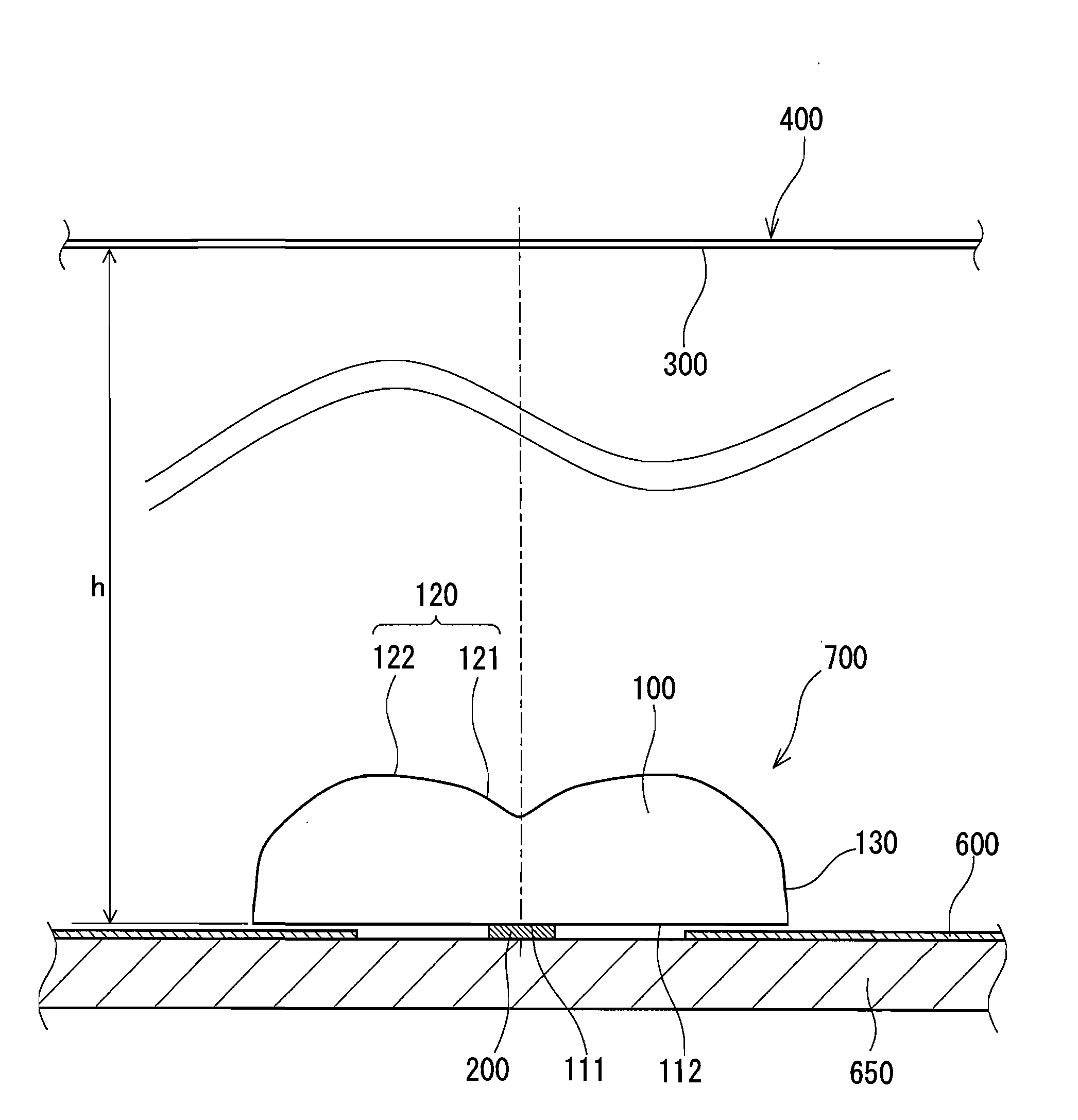
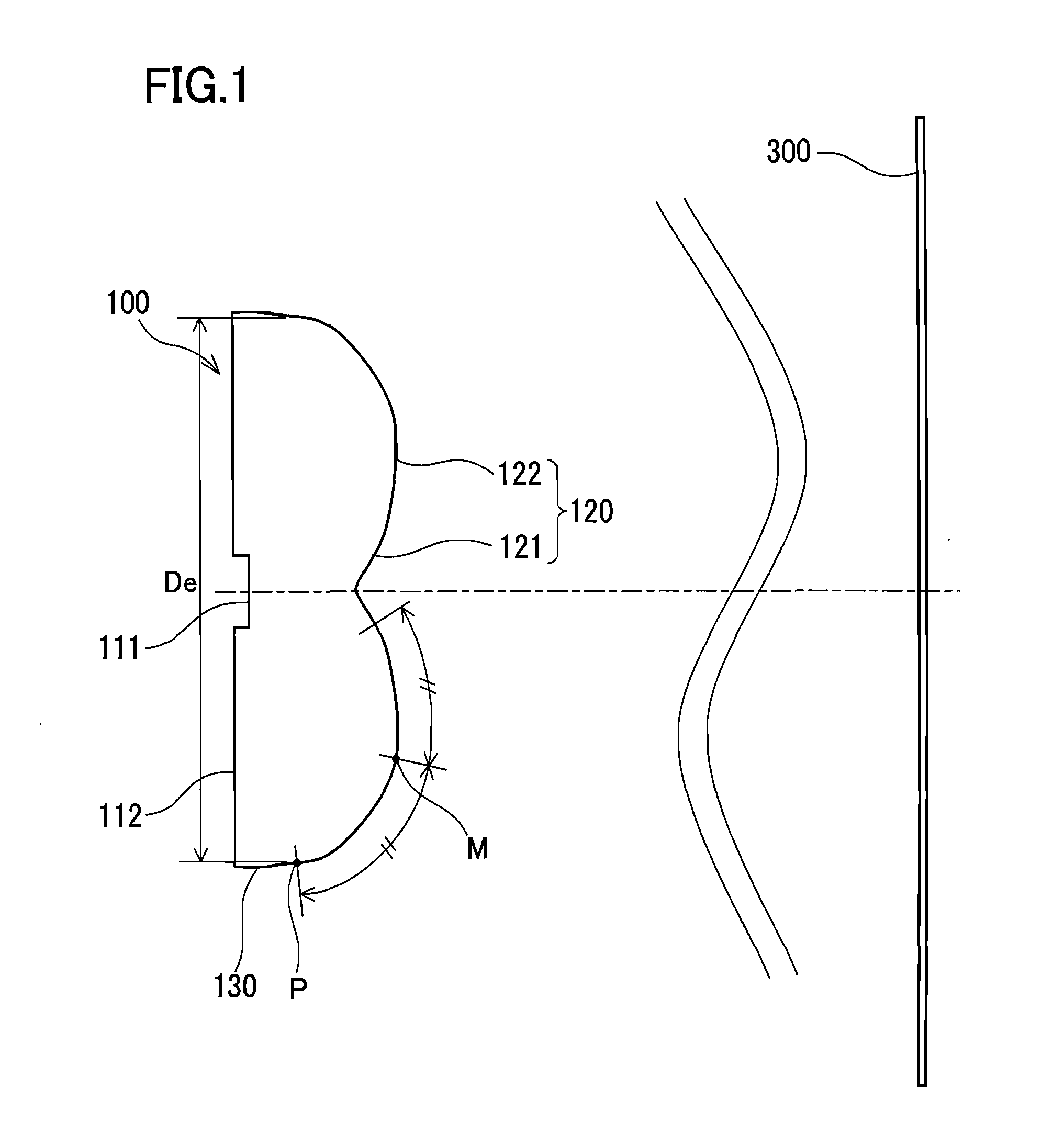
[0052]An illuminating lens according to the first embodiment of the present invention will be described with reference to the accompanying drawings. FIG. 1 is a schematic diagram of an illuminating lens 100 according to the first embodiment. The illuminating lens 100, which is disposed between a light source (not shown in FIG. 1) having directivity and a surface to be irradiated 300, spreads light emitted from the light source and emits the spread light to the surface to be irradiated 300. That is, the illuminating lens 100 widens the range of transmission directions for light from the light source. In the illuminance distribution on the surface to be irradiated 300, the illuminance is greatest on the optical axis A that is the design center line of the illuminating lens 100 and decreases almost monotonically toward the edge. The light source and the illuminating lens 100 are disposed so that their optical axes coincide with each other.
[0053]Specifically, the illuminating lens 100 h...
second embodiment
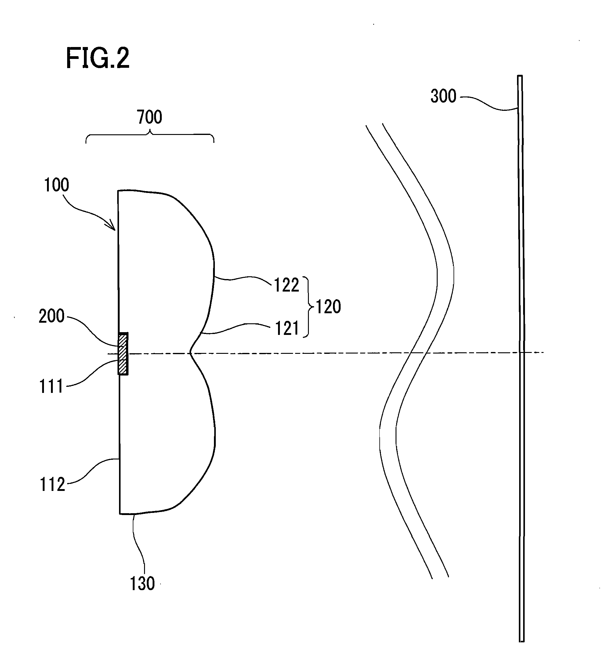
[0088]FIG. 2 is a schematic diagram of a lighting device 700 according to a second embodiment of the present invention. This lighting device 700 includes a light emitting diode 200 for emitting light, and the illuminating lens 100 described in the first embodiment for spreading light emitted from the light emitting diode 200 so that the surface to be irradiated 300 is irradiated with the spread light.
[0089]The light emitting diode 200 is in contact with the light entrance surface 111 of the illuminating lens 100 via a bonding agent, and connected optically to the light entrance surface 111. The light that has exited the illuminating lens 100 through the light exit surface 120 reaches the surface to be irradiated 300, and thus the surface to be irradiated 300 is illuminated with that light.
[0090]Light generation in the light emitting diode 200 has no directivity in itself, and a light emitting region has a refractive index of at least 2.0. When light from the light emitting region en...
example 1
[0099]An illuminating lens of Example 1 has a shape corresponding to that shown in FIG. 3. Example 1 is an example of an illuminating lens designed to widen the range of transmission directions for light from a 0.5 mm cubic-shaped light emitting diode as a light source. Table 1 shows the surface data of the illuminating lens of Example 1, and Table 2 shows the aspherical surface data thereof.
TABLE 1Surface dataSurface numberrdnObject surface∞0.9641.411*8.373E−137.036Image surface∞
TABLE 2Aspherical surface dataFirst surfaceK = −1.0268E+01, A3 = 1.9628E+00, A4 = −8.3686E+00,A5 = 1.9670E+01 A6 = −3.6276E+01, A7 = 4.6681E+01,A8 = −3.0918E+01, A9 = −1.0909E−01 A10 = 1.0608E+01,A11 = −7.0489E−03, A12 = −4.5201E+00, A13 = 1.2256E−02A14 = 1.4688E+00, A15 = 3.4825E−04, A16 = −3.1939E−01,A17 = −7.9209E−04 A18 = 4.0742E−02, A19 = 3.5721E−05,A20 = −2.2613E−03
[0100]FIG. 8 shows the illuminance distribution on the surface to be irradiated obtained by calculation assuming that the illuminating len...
PUM
 Abstract
Description
Claims
Application Information
 - R&D
- Intellectual Property
- Life Sciences
- Materials
- Tech Scout
- Unparalleled Data Quality
- Higher Quality Content
- 60% Fewer Hallucinations
Browse by: Latest US Patents, China's latest patents, Technical Efficacy Thesaurus, Application Domain, Technology Topic, Popular Technical Reports.
© 2025 PatSnap. All rights reserved.Legal|Privacy policy|Modern Slavery Act Transparency Statement|Sitemap|About US| Contact US: help@patsnap.com