Device for optically detecting position and/or orientation of objects comprising at least one linear sensor

a technology of optical detection and linear sensors, applied in the field of optical detection position and orientation of objects in space, can solve the problems of several cameras and several sensors, the static positioning performance of sensors is not modified, and the solution exhibits a certain number of drawbacks and limitations

Active Publication Date: 2010-07-29
THALES SA
View PDF9 Cites 11 Cited by
  • Summary
  • Abstract
  • Description
  • Claims
  • Application Information

AI Technical Summary

Benefits of technology

[0030]The invention proposes to solve this problem, notably by relaxing the planarity constraint on the sensors disposed on the mobile object.

Problems solved by technology

The determination of the positioning of a point in space and the determination of the attitude of an arbitrary object are problems relating to numerous technical fields.
These sensors do not modify the static positioning performance of the detection devices cited above.
Nevertheless, these solutions exhibit a certain number of drawbacks and limitations, particularly in the aeronautical field.
Moreover, these same devices require several cameras and several sensors.
The position calculations demand numerous resources and the real-time analysis is complex to implement.
Moreover, one drawback results from the diffusion in the zone of detection of the light of the LEDs and another drawback results from the disturbances of the luminous environment of the cockpit due to the sun or to stray reflections on the canopy.
As regards electromagnetic posture detection devices, robust solutions are difficult to implement.
In particular, in the aeronautical field, stray radiations and electromagnetic disturbances may degrade the performance of the existing systems.
A drawback of such a sensor is the constraint of accuracy of mechanical transfer of the sensors onto their support.
Moreover, this disposition contributes to the compounding of errors of mechanical tolerancing, for example in the positioning of the sensor on the helmet and as regards the accuracy of the sensor.

Method used


Image

  • Device for optically detecting position and/or orientation of objects comprising at least one linear sensor
  • Device for optically detecting position and/or orientation of objects comprising at least one linear sensor
  • Device for optically detecting position and/or orientation of objects comprising at least one linear sensor

Examples


Embodiment Construction

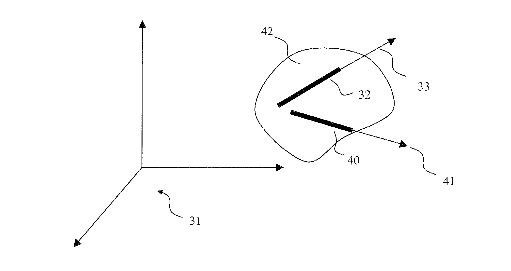
[0079]A principle of the invention relates to the determination of the posture of a mobile part in space on the basis of a fixed part comprising an image projector. The mobile part comprises sensors and the images are projected in a zone comprising the sensors.

[0080]The effectiveness of such a system for detecting motion of a mobile part relies on the form, the number and the disposition of the sensors on the mobile part, moreover it relies on the sharpness of the projected images, of the form and of the brightness of the projected test grids.

[0081]Other characteristics can be taken into account in such a system notably with regard to the descriptions of the following two published patent applications:[0082]Patent application FR 2 905 456, detailing the principle according to which an image projector makes it possible to ascertain the motion of an object comprising a certain number of sensors forming clusters.[0083]Patent application FR 2 905 455, detailing a method for detecting th...


PUM


Abstract

The electro-optical system for determining the attitude of a mobile part comprises a fixed part and a mobile part, the fixed part being linked rigidly with at least one virtual image plane.
The mobile part is linked rigidly with at least one first linear electro-optical device defining a first direction vector, the calculation of the position of the vanishing point of the projection of the straight line comprising the first direction vector in the image plane determining a first direction, representing the direction of the mapping of the first direction vector in the image plane, and a first choice of a first point of the projection in the image plane of the straight line comprising the first direction vector determining a first sense, representing the sense of the mapping of the first direction vector in the image plane.

Description

PRIORITY CLAIM[0001]This application claims priority to French Patent Application Number 08 05315, entitled Dispositif De Detection Optique De Position Et / Ou D'Orientation D'Objets Comprenant Au Moins Un Capteur Lineaire, filed on Sep. 26, 2008.TECHNICAL FIELD[0002]The present invention relates to the field of devices for optically detecting position and orientation of objects in space. It applies more particularly in the aeronautical field where in this case the detected object is a pilot helmet.BACKGROUND OF THE INVENTION[0003]The determination of the positioning of a point in space and the determination of the attitude of an arbitrary object are problems relating to numerous technical fields.[0004]The various solutions generally afforded must resolve any ambiguity in position or attitude, cater for more or less severe dynamics in terms of displacement, speeds and accelerations of the systems and satisfy high accuracy, in particular in the aeronautical field.[0005]In systems for d...

Claims


Application Information

Patent Timeline
Patent Type & Authority Applications(United States)
IPC IPC(8): G06T7/20
CPCG01S5/163
Inventor ROUZES, SIEGFRIEDLACOSTE, LILIAN
Owner THALES SA
Why Eureka
Try Eureka