
Cleaning unit, process cartriedge incorporating same, and image forming apparatus incorporating the cleaning unit

a technology of cleaning unit and process, which is applied in the direction of electrographic process apparatus, instruments, optics, etc., can solve the problems of permanent bent blades of known cleaning units, and insufficient removal of residual toner

Inactive Publication Date: 2010-07-29
RICOH KK
View PDF27 Cites 25 Cited by
  • Summary
  • Abstract
  • Description
  • Claims
  • Application Information

AI Technical Summary

Benefits of technology

[0009]Example aspects of the present patent application provide a cleaning unit that can effectively prevent causing compression set of a cleaning blade made of rubber material.

Problems solved by technology

However, over time the pair of rubber blades of the known cleaning unit is susceptible to compression set, in which the blades become permanently bent.
This gap is likely to cause insufficient removal of residual toner and uneven regulation of the amount of lubricant.
Moreover, if compression set occurs, because the above-described rubber blades are disposed on either side of the lubricant applicator, that is, disposed upstream and downstream from the lubricant applicator in the direction of rotation of the image carrier, any residual toner remaining on the surface of the image carrier after passing under the upstream rubber blade may need to be dammed by the downstream rubber blade even as the downstream rubber blade regulates the amount of lubricant, which may damage the downstream rubber blade, allowing toner to mix with the lubricant.

Method used


Image

  • Cleaning unit, process cartriedge incorporating same, and image forming apparatus incorporating the cleaning unit
  • Cleaning unit, process cartriedge incorporating same, and image forming apparatus incorporating the cleaning unit
  • Cleaning unit, process cartriedge incorporating same, and image forming apparatus incorporating the cleaning unit

Examples


example

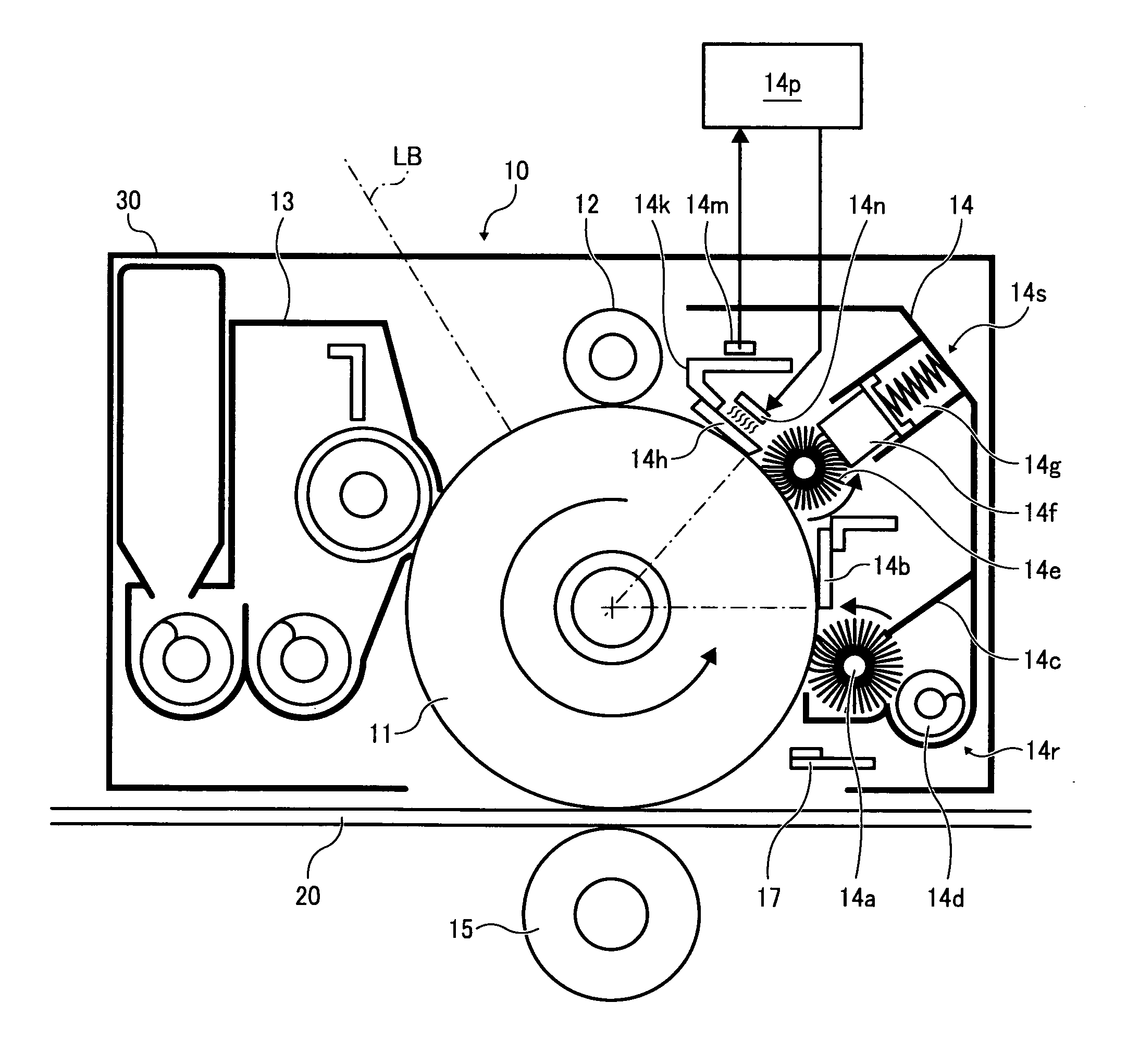
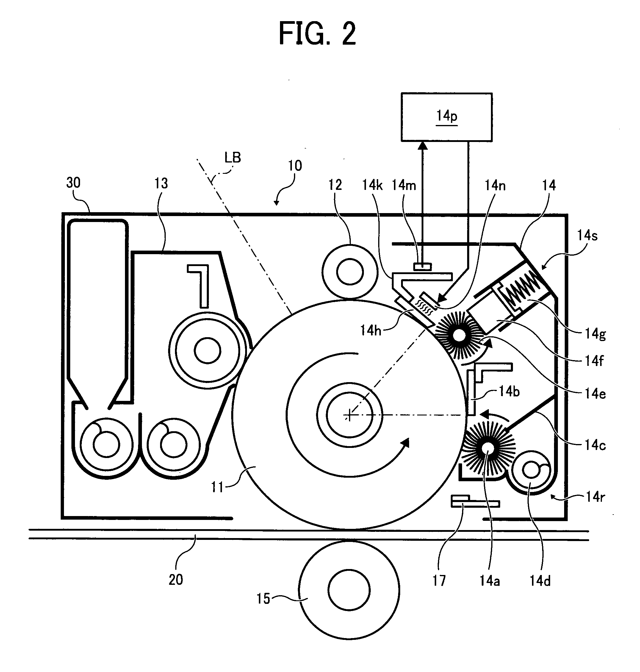
[0089]Parameters of the lubricant regulating rubber blade 14h and units and components disposed therearound are set as follows:

[0090]Consumption amount of lubricant 14f (see FIG. 2) that includes zinc stearate scraped by the lubricant application fur brush 14e (see FIG. 2): 120 mg / Km to 150 mg / Km per distance of movement of the photoconductor drum 11;

[0091]The lubricant regulating rubber blade 14h: Urethane rubber having rubber hardness of 70 degrees (JIS A hardness);

[0092]Thickness of the lubricant regulating rubber blade 14h (indicated as “t” in FIG. 3): 1.5 mm;

[0093]Amount of projection (indicated as “L” in FIG. 3) or distance between a distal end surface of the supporting member 14k and a distal end surface of the lubricant regulating rubber blade 14h: 6 mm;

[0094]Initial contact angle (indicated as “α” in FIG. 3) or angle of the lubricant regulating rubber blade 14h inclined in a clockwise direction from the tangent line (indicated as “TL” in FIG. 3) at a contact point of the su...


PUM


Abstract

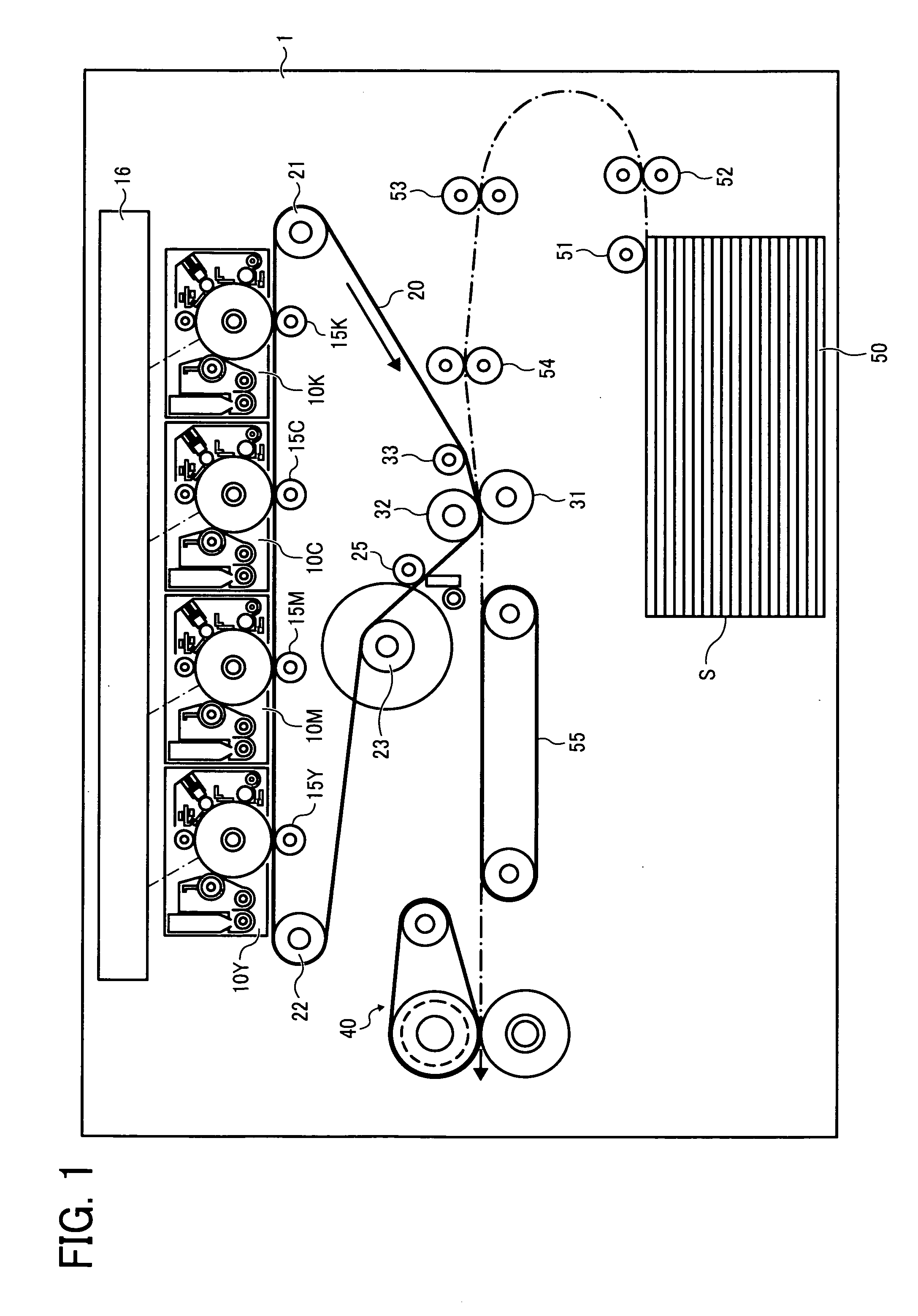
A cleaning unit, which can be incorporated in a process cartridge removably installable in an image forming apparatus, includes a lubricant applicator to apply lubricant to an image carrier, a first blade disposed upstream from the lubricant applicator in a direction of rotation of the image carrier with its distal end held in contact with the image carrier to remove residual toner remaining on the image carrier, a second blade disposed downstream from the lubricant applicator in the direction of rotation of the image carrier with its distal end held in contact with the image carrier to regulate the amount of lubricant applied to the image carrier, a temperature measuring member to measure a temperature of or near the second blade, a heater, and a temperature controller to control the heater to heat the second blade so that the measured temperature falls within a given set temperature range.

Description

CROSS-REFERENCE TO RELATED APPLICATIONS[0001]The present patent application claims priority pursuant to 35 U.S.C. §119 from Japanese Patent Application No. 2009-012476, filed on Jan. 23, 2009 in the Japan Patent Office, which is hereby incorporated by reference herein in its entirety.BACKGROUND OF THE INVENTION[0002]1. Field of the Invention[0003]Example embodiments of the present patent application generally relate to a cleaning unit, a process unit incorporating the cleaning unit, and an image forming apparatus incorporating the cleaning unit.[0004]2. Discussion of the Related Art[0005]Image forming apparatuses typically include a cleaning unit disposed together with a rotatable image carrier that bears an image. The cleaning unit includes, for example, a pair of rubber blades disposed in slidable contact with the rotatable image carrier. A lubricant applicator that applies lubricant to the image carrier is disposed between the pair of rubber blades, such that one of the pair of r...

Claims


Application Information

Patent Timeline
Patent Type & Authority Applications(United States)
IPC IPC(8): G03G21/20G03G21/16
CPCG03G21/0011G03G2221/1621G03G21/1814G03G21/007
Inventor SHINTANI, TAKESHIKUWABARA, NOBUOHATORI, SATOSHITOMITA, DAISUKEKOSUGE, AKIOOZAWA, YOSHINORIKAWAHARA, SHINICHIMURAISHI, TAKAYAAKIBA, YASUSHI
Owner RICOH KK
Learn More