Belt driving device, fixing device, and image forming apparatus

a technology of fixing device and fixing belt, which is applied in the direction of electrographic process, gearing, instruments, etc., can solve the problems of axial the shifting of the fixing belt, so as to prevent shifting and meandering of the fixing belt reliably and cheaply. , the effect of preventing the shifting and meandering of the fixing bel

Inactive Publication Date: 2010-07-29
RICOH KK
View PDF24 Cites 18 Cited by
  • Summary
  • Abstract
  • Description
  • Claims
  • Application Information

AI Technical Summary

Benefits of technology

[0018]In view of the foregoing, illustrative embodiments described herein provide a durable belt driving device capable of inexpensively and reliably prev

Problems solved by technology

In the fixing device having the above-described configuration, a slight shift in the alignment of multiple rollers around which the fixing belt is wound and the action of the nip formed between the fixing roller and the pressure roller with the fixing belt therebetween can cause axial shifting of the fixing belt.
Consequently, shifting of the fixing belt more often occurs at the nip between the fixing roller and the pressure roller, and as a result, the problem of preventing shifting of the fixing belt assumes even greater importance.
However, shifting of the fixing belt caused by the action of the nip formed between the fixing roller and the pressure roller with the fixing belt therebetween may not be solved by the above-described fixing device because it is assumed that, in the above-described fixing device, shifting of the fixing belt is corrected only when the movement of the driven roller in the thrust direction is in the opposite direction from the shifting of the fixing belt.
Therefore, shifting of the fixing belt caused by factors other than twisting of the rollers

Method used


Image

  • Belt driving device, fixing device, and image forming apparatus
  • Belt driving device, fixing device, and image forming apparatus
  • Belt driving device, fixing device, and image forming apparatus

Examples


Embodiment Construction

[0042]In describing illustrative embodiments illustrated in the drawings, specific terminology is employed for the sake of clarity. However, the disclosure of this specification is not intended to be limited to the specific terminology so selected, and it is to be understood that each specific element includes all technical equivalents that operate in a similar manner and achieve a similar result.

[0043]Reference is now made to the drawings, wherein like reference numerals designate identical or corresponding parts throughout the several views.

[0044]A description is now given of a belt driving device and a fixing device according to illustrative embodiments.

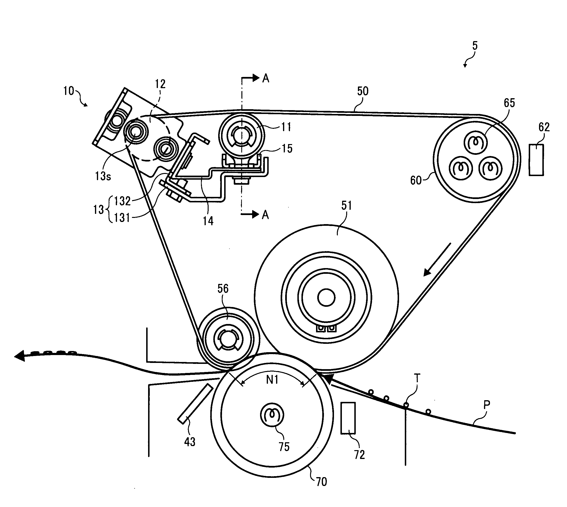
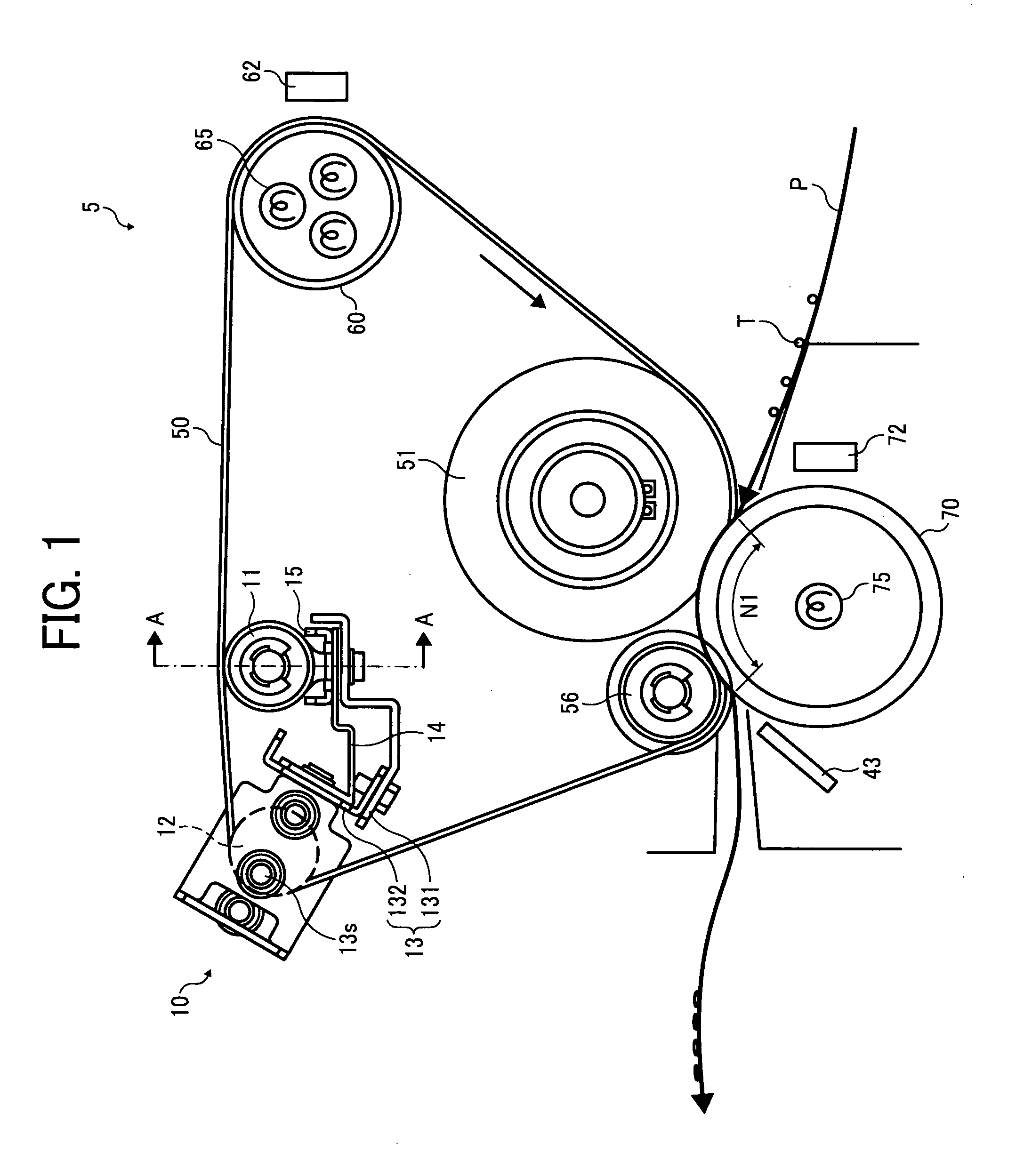
[0045]FIG. 1 is a vertical cross-sectional view illustrating an example of a configuration of a fixing device 5 according to illustrative embodiments.

[0046]The fixing device 5 includes a cylindrical fixing roller 51; a separation roller 56; a driven roller unit 10; a heat roller 60; a fixing belt 50 wound around the fixing roller ...


PUM


Abstract

A belt driving device including a rotatable seamless belt wound around rotatable driven rollers and one or multiple rollers, and a driven roller unit including the rotatable driven rollers. The driven roller unit includes a detection roller rotatably driven, a surface of which contacts an inner surface of the belt to slide in a direction of a rotary shaft thereof when shifting occurs on the belt in a width direction thereof; a correction roller rotatably driven, a rotary shaft of which is rotatably supported to displace around any single point on the rotary shaft thereof while a surface thereof contacts the inner surface of the belt; and a conversion unit to convert displacement of the detection roller in the direction of the rotary shaft of the detection roller into angular displacement of the correction roller in a direction of rotation of the correction roller.

Description

PRIORITY STATEMENT[0001]The present patent application claims priority from Japanese Patent Application No. 2009-015389, filed on Jan. 27, 2009 in the Japan Patent Office, which is hereby incorporated herein by reference in its entirety.BACKGROUND[0002]1. Technical Field[0003]Illustrative embodiments described in this patent specification generally relate to a belt driving device to rotate a belt; a fixing device using the belt driving device to convey a recording medium and to apply heat to the recording medium; and an image forming apparatus including the fixing device.[0004]2. Description of the Related Art[0005]Related-art image forming apparatuses, such as copiers, printers, facsimile machines, or multifunction devices having two or more of copying, printing, and facsimile functions, typically form a toner image on a recording medium (e.g., a sheet) according to image data using an electrophotographic method. In such a method, for example, a charger charges a surface of an imag...

Claims


Application Information

Patent Timeline
IPC IPC(8): G03G15/20F16H9/04
CPCF16H7/02G03G15/2064G03G2215/00156G03G2215/2038G03G2215/2006G03G2215/2032G03G2215/00168
Inventor YAMADA, MASAMICHI
Owner RICOH KK
Why Eureka
Try Eureka