Tap Holder

Active Publication Date: 2009-08-20
BIG DAISHOWA CO LTD
View PDF26 Cites 12 Cited by
  • Summary
  • Abstract
  • Description
  • Claims
  • Application Information

AI Technical Summary

Benefits of technology

[0017]According to the invention, an error of synchronizing spindle feeding and rotation of a machine tool spindle can be absorbed by a simple constitution by producing a small amount of movement in an axial direction between a tapper body and a tap collet.
[0018]Further, the tapper body and the tap collet as well as the lo

Problems solved by technology

However, in actual tapping, owing to a phenomenon referred to as servo delay, an amount of running a tap while machining by rotating becomes larger, or conversely smaller than a tap pitch per rotating the machine tool spindle, tapping is progressed fast or slow by an incoincidence of spindle feeding and rotation, and therefore, a deviation is brought about among an amount of spindle feeding per rotation and a tap pitch.
However, although a synchronization accuracy of the machine tool is promoted, for example, when a spindle feeding direction and a spindle rotating direction are switched in order to draw a tap from a subject work, rotation of a machine tool spindle does not synchronize with spindle feeding and a small sift of the tap in an axial direction cannot completely be excluded from being brought about, and therefore, there is a drawback of enlarging or leaning a screw thread.
However, the constitutions described in Patent References 1 through 3 pose a problem that structures are complicated in any of t

Method used


Image

  • Tap Holder
  • Tap Holder
  • Tap Holder

Examples


first embodiment

[0043]A first embodiment of the invention will be explained in reference to the drawings as follows.

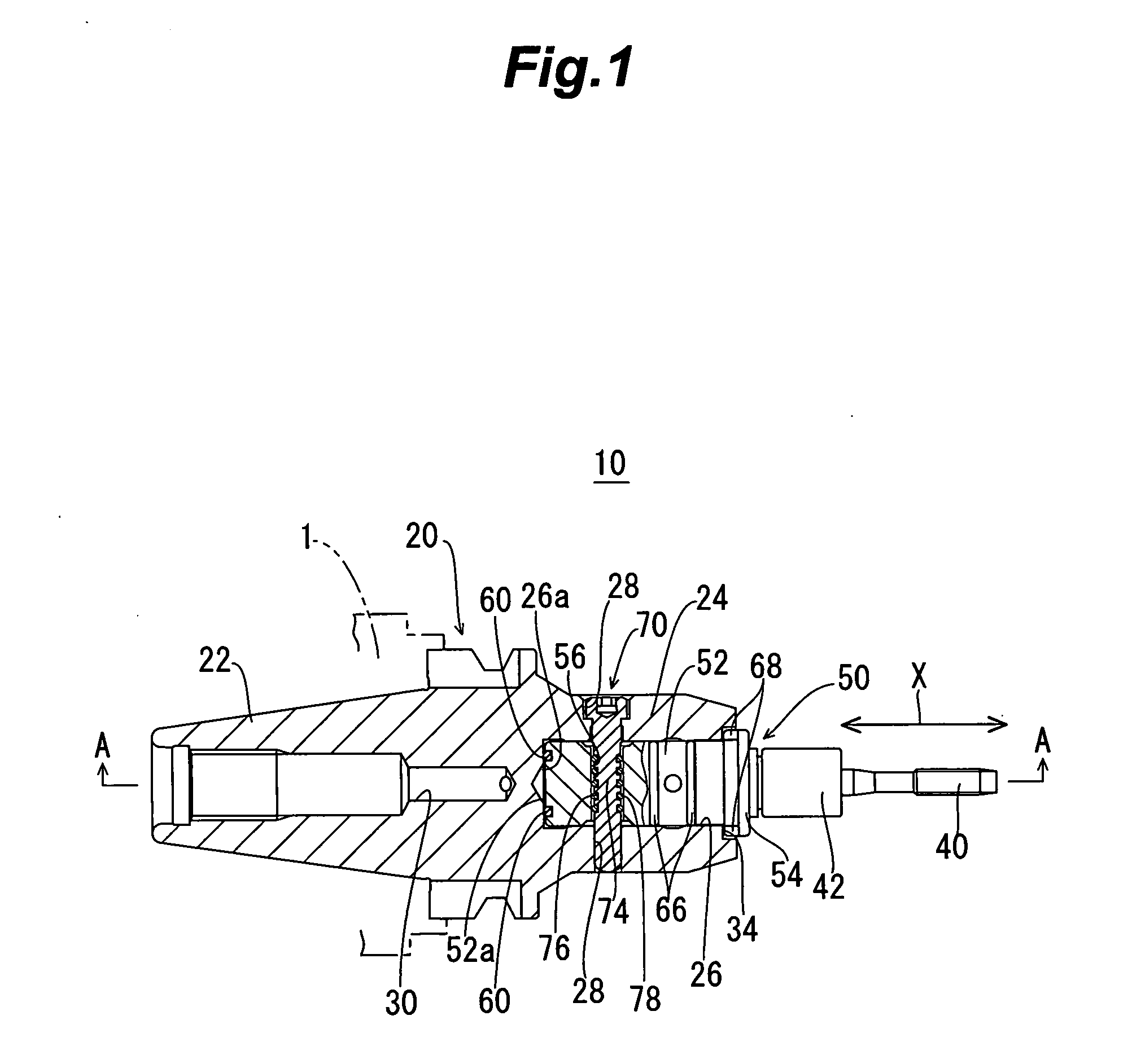
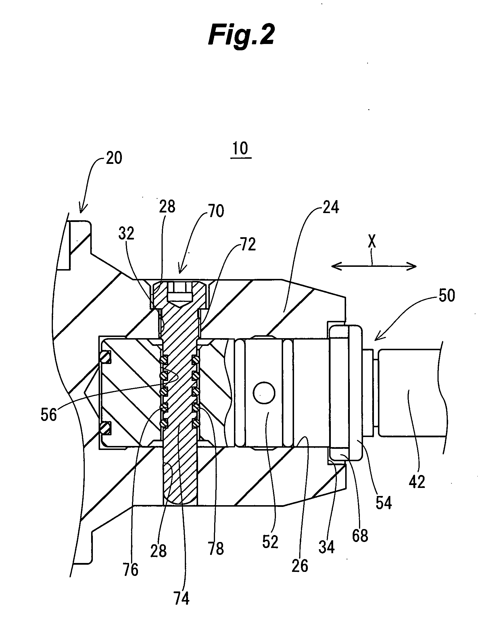
[0044]FIG. 1 is a sectional view of a tap holder 10 according to a first embodiment of the invention, FIG. 2 is a sectional view enlarging an essential portion of the tap holder 10, FIG. 3 is a sectional view taken along a line A-A of FIG. 1, and FIG. 4 is a disassembled view of the tap holder 10.

[0045]The tap holder 10 according to the embodiment is a tap holder for mounting a tap 40 to a machine tool having a tap synchronizingly feeding mechanism, having a tapper body 20 including a shank portion 22 attachably and detachably mounted to a spindle 1 of the machine tool, a tap collet 50 having a tap holding member 42 for holding the tap 40 at a front end thereof, and attachably and detachably attached to the tapper body 20, and a locking member 70 for connecting the tap collet 50 to the tapper body 20.

[0046]The tapper body 20 is provided with an outer cylinder portion 24 integrally wit...

second embodiment

[0060]A second embodiment will be explained in reference to FIG. 8 through FIG. 10. Elements the same as or corresponding to those of the first embodiment are attached with the same notations and a duplicated explanation thereof will be omitted. FIG. 8 through FIG. 10 are sectional views enlarging an essential portion of the tap holder 10 according to the embodiment.

[0061]Although according to the first embodiment, the elastic member 78 is arranged at the first recessed portion 76 provided at the locking member 70, according to the tap holder 10 of the embodiment, an elastic member unit 80 including an elastic member 82 is interposed between the locking shaft portion 74 and the tap collet 50.

[0062]Specifically, the elastic member unit 80 includes, for example, a cylinder member 84 in a circular cylindrical shape formed by a material having a rigidity larger than that of the elastic member 82 having a material the same as that of the tap collet 50 and the elastic member 82 arranged a...

third embodiment

[0066]Next, a third embodiment will be explained in reference to FIG. 11. Elements the same as or corresponding to those of the first embodiment and the second embodiment are attached with the same notations and a duplicated explanation thereof will be omitted. FIG. 11 is a sectional view enlarging an essential portion of the tap holder 10 according to the embodiment.

[0067]A characteristic of the embodiment resides in that the elastic member for absorbing the difference between the amount of moving the tapper body 20 and the amount of spontaneously running the tap 40 is arranged at the tap collet 50.

[0068]That is, as shown by FIG. 11, the shaft portion 52 of the tap collet 50 is provided with a third recessed portion 90 penetrated in a diameter direction at a position in correspondence with the through hole 28 provided at the tapper body20, and by inserting the shaft portion 52 into the attaching hollow portion 26, the through hole 28 at the tapper body 20 and the third recessed por...


PUM

PropertyMeasurementUnit
Thicknessaaaaaaaaaa
Elasticityaaaaaaaaaa

Abstract

It is an object of the invention to provide a tap holder in which even when an error is brought about in synchronizing spindle feeding and rotation of a tapper body and a tap collet of a tap holder in correspondence with a machine tool spindle, the synchronization can be established by absorbing the error by a simple constitution. As means therefor, the tap holder is characterized in that a tapper body and a tap collet are inserted by a locking member at portions of the tapper body and the tap collet overlapping each other, and the tap collet is fixed to the tapper body by engaging the locking member with at least one of the tap collet and the tapper body in a state of being interposed with an elastic member on both sides thereof in an axial direction X.

Description

BACKGROUND OF THE INVENTION[0001]The present invention relates to a tap holder for holding a tap for tapping and for equipping with a machine tool spindle.[0002]When tapping is carried out by a machine tool by utilizing synchronization with feeding and rotation of a machine tool spindle, rotation and feeding of the machine tool spindle are controlled to synchronize in accordance with a pitch of a tap. However, in actual tapping, owing to a phenomenon referred to as servo delay, an amount of running a tap while machining by rotating becomes larger, or conversely smaller than a tap pitch per rotating the machine tool spindle, tapping is progressed fast or slow by an incoincidence of spindle feeding and rotation, and therefore, a deviation is brought about among an amount of spindle feeding per rotation and a tap pitch. Although in a background art, the incoincidence is prevented by providing floats on both sides in an axial direction of a tap holder, in recent years, the floats are el...

Claims


Application Information

Patent Timeline
IPC IPC(8): B21D53/24
CPCB23B31/08Y10T408/95Y10T279/17837Y10T279/17923Y10T279/17846Y10T408/94Y10T279/17017B23B31/083B23G1/46B23G1/48B23Q3/12
Inventor KOMINE, TSUYOSHISURUGA, HIROKAZU
Owner BIG DAISHOWA CO LTD
Why Eureka
Try Eureka