
Lifting device for the assembly of a wind turbine

a technology for lifting devices and wind turbines, which is applied in the manufacture of machines/engines, lifters, and final products. it can solve the problems of not providing the same or similar inventions of these inventions, and the assembly of a wind turbine is ever more complicated and costly

Inactive Publication Date: 2010-07-29
GAMESA INNOVATION & TECH SA
View PDF4 Cites 20 Cited by
  • Summary
  • Abstract
  • Description
  • Claims
  • Application Information

AI Technical Summary

Benefits of technology

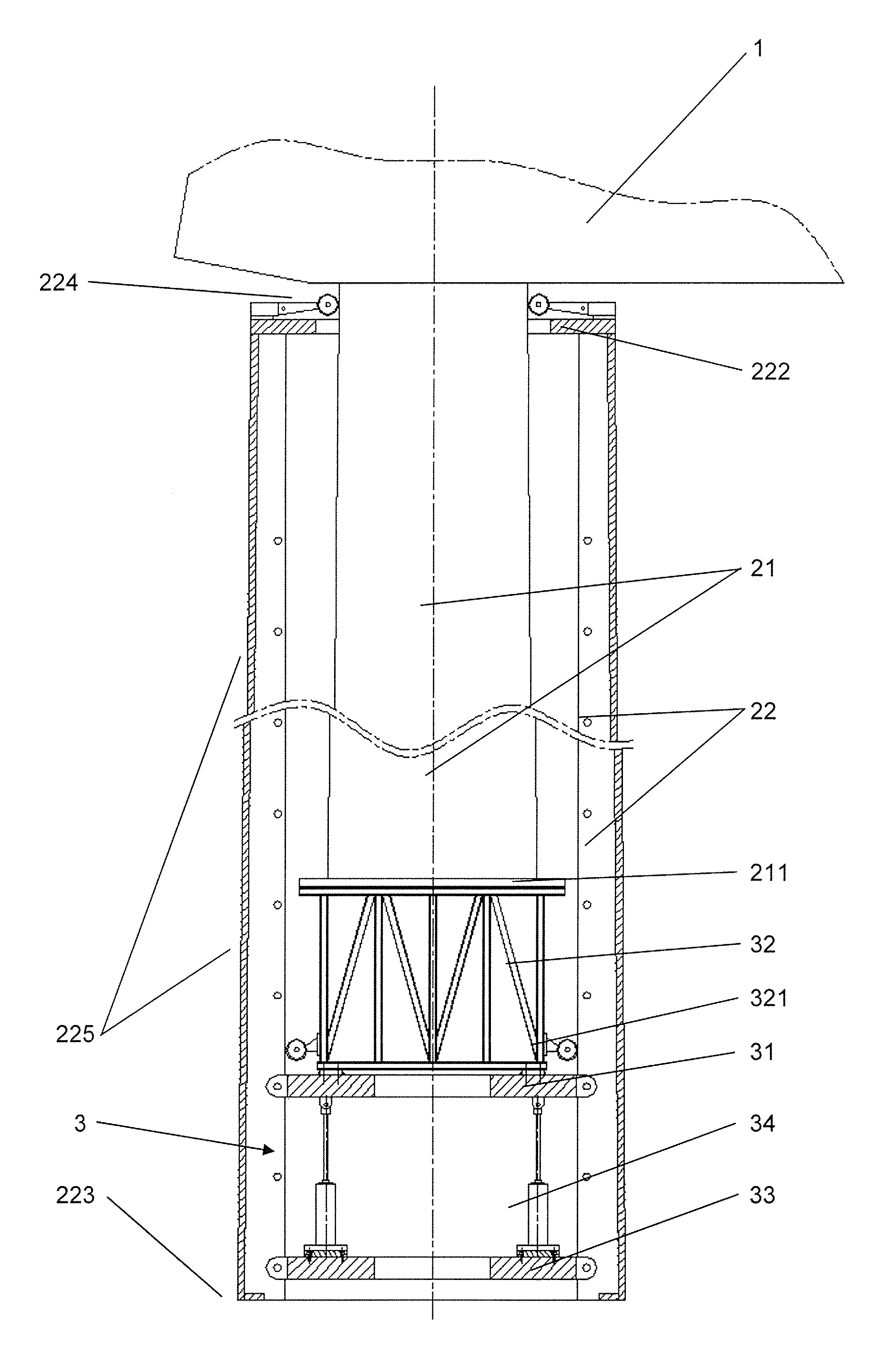
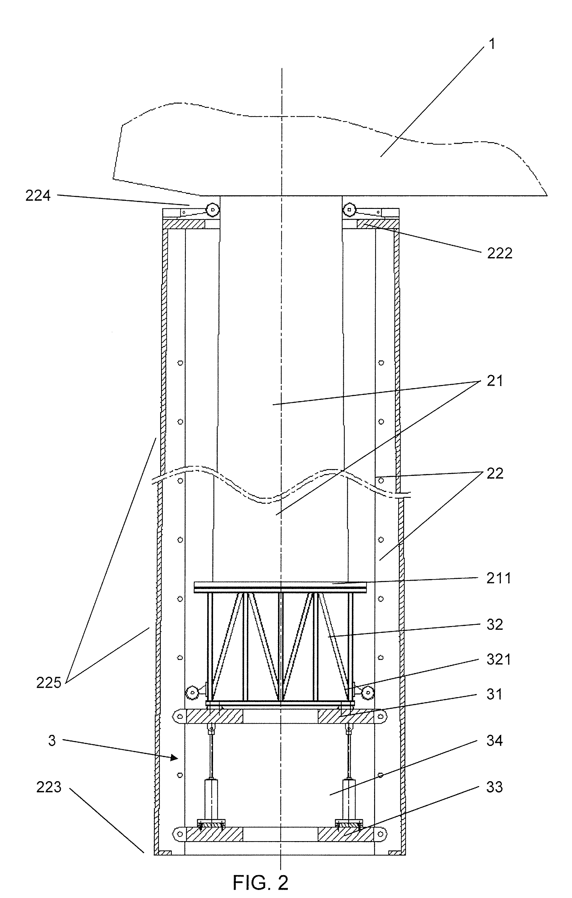
[0014]The upper platform consists of a ring-shaped support where the supporting structure and the lifting device cylinders are secured. It also provides fixtures to the anchoring beams on the outer perimeter of the ring. The connection to the supporting structure is carried out by screwing the supporting structure to the upper side of the platform, and the cylinders are fixed to the lower side of the platform using pivoting fixtures. The connection methods for the upper platform are adapted to the shape of the anchoring beams of the lower part of the tower, in such a way that they allow the movement of said fixtures along the anchoring beams and therefore the movement of the upper platform along the lower part of the tower, while allowing for the platform to be fixed at certain points of said anchoring beams. Finally, the platform may be comprised of various independent parts, which enable it to be transported, installed and uninstalled in a simple way.

Problems solved by technology

As a result, the transport of the towers must be divided into parts, and some parts even into sections, making the assembly of a wind turbine ever more complicated and costly.
However, none of these inventions are similar to nor do they provide the advantages of the lifting device for the assembly of a wind turbine which is described below.

Method used


Image

  • Lifting device for the assembly of a wind turbine
  • Lifting device for the assembly of a wind turbine
  • Lifting device for the assembly of a wind turbine

Examples


Embodiment Construction

[0010]The invention describes a lifting device and an assembly method for the erection of a tower divided into at least one upper part and another lower part substituting large assembly cranes for a conventional crane. Said crane places the upper part of the tower vertically on the lifting device and then places the sections of the lower part of the tower around said upper part, in such a way that the fixtures to the anchoring beams of the lifting device are embedded into the anchoring beams which are arranged in the inside area of the lower part of the tower and serve to guide and fix the lifting device along its route. Then, the lifting device fixes its lower platform to the anchoring beams and separates the upper platform using cylinders located between both platforms, it then fixes the upper platform to the anchoring beams and releases the lower platform in order to move it closer to the upper platform using said cylinders, and it continues successively until the lower flange of...


PUM


Abstract

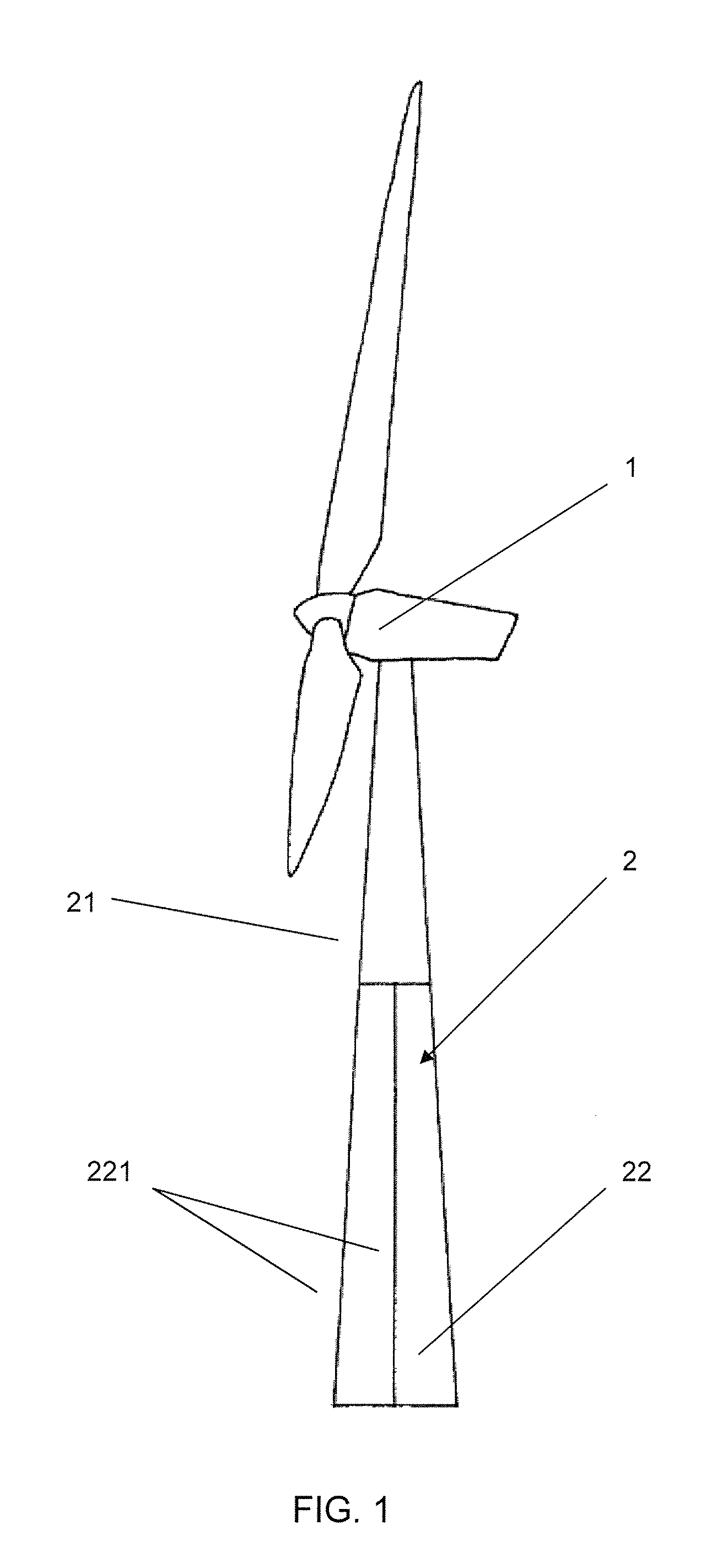
Lifting device for the assembly of a wind turbine of which the top part of the tower (21) is fixed to the supporting structure (32) located above the upper platform (31) of the lifting device (3). The sections (221) of the lower part (22) of the tower are then installed, in such a way that the lifting device (3) is embedded in the anchoring beams (225) of the lower part (22). 10.In order to lift the upper part (21) of the tower, the upper platform (31) is separated from the lower platform (33) using cylinders (34) between said platforms, the upper platform (31) is fixed to the anchoring beams (225), the lower platform (33) is freed from the anchoring beams (225), the platforms (31, 33) are brought closer together and the lower platform (33) is anchored to said beams (225). Continuing successively until the flanges (211, 222) of the parts (21, 22) of the tower make contact.

Description

FIELD OF THE INVENTION[0001]The invention relates to a lifting method and lifting device for the erection of hollow towers comprised of more than one part, and in particular, to a lifting method and lifting device for carrying out the assembly of a wind turbine.BACKGROUND OF THE INVENTION[0002]As wind turbines tend to provide more power, the weight and dimensions of their components increase considerably and, consequently, the towers become taller and more robust. As a result, the transport of the towers must be divided into parts, and some parts even into sections, making the assembly of a wind turbine ever more complicated and costly. One way of reducing the high costs of the wind turbine assembly process consists in the substitution of large sized cranes for conventional cranes and for assembly devices. Below is a state of the art summary relating to the inventions used for the assembly of towers and wind turbines.[0003]Patent application U.S. Pat. No. 6,782,667 proposes a wind t...

Claims


Application Information

Patent Timeline
IPC IPC(8): E04H12/34
CPCE02D27/42F03D1/001F03D11/04Y02E10/728F05B2240/916F05B2260/301F05B2230/61E02D27/425F03D13/10F03D13/20F03D13/40Y02E10/72Y10S187/90Y02P70/50E04H12/18E04H12/34
Inventor CHRISTENSEN, MOGENS
Owner GAMESA INNOVATION & TECH SA
Learn More